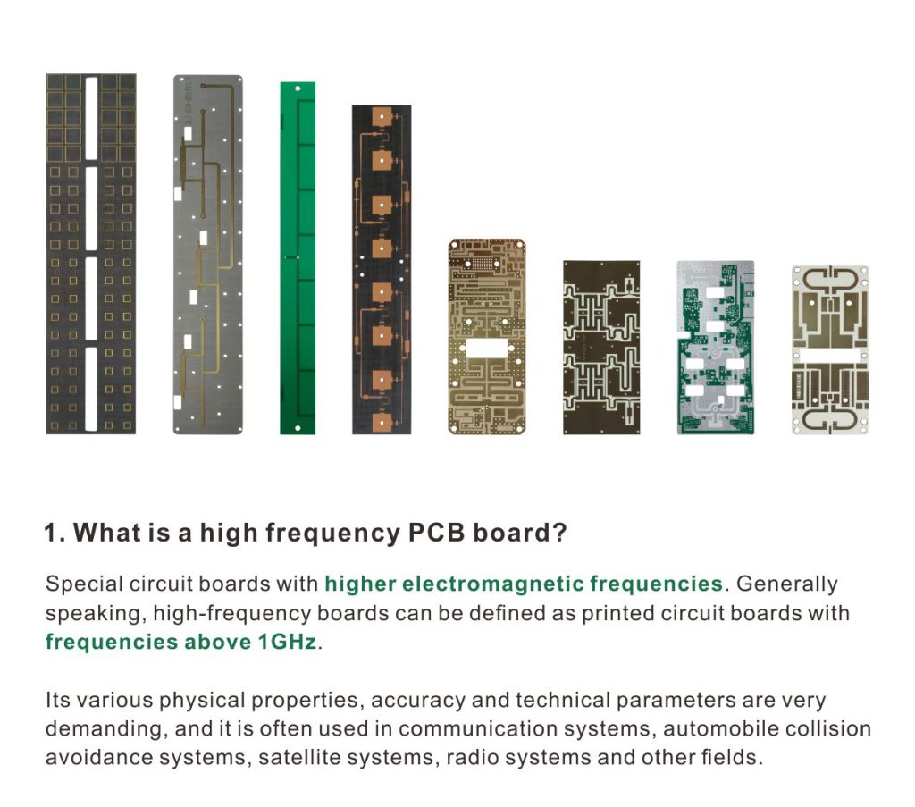
The RO5880 substrate material itself is typically light-colored or transparent (nearly colorless), but once fabricated into a PCB, its solder mask comes in a variety of colors. Common options include green, red, blue, white, purple, and black. Specific details are as follows:
Natural color of the substrate material: RT/Duroid RO5880 material is typically composed of PTFE and glass fiber. As a substrate for high-frequency circuits, the material itself is usually black. However, in practical applications, the substrate material is usually processed into a PCB (printed circuit board), at which point its color is primarily determined by the solder mask.
Solder Mask Color: During the PCB manufacturing process, the solder mask is applied to the substrate surface to protect the circuit from damage caused by oxidation, corrosion, and short circuits. PCBs made from RO5880 dielectric substrates come in a variety of solder mask colors, with common options including green, red, blue, white, purple, and black. These colors not only enhance aesthetics but also help distinguish different circuit areas or functional modules to some extent.
Factors influencing color selection: The choice of solder mask color typically depends on design requirements, manufacturing processes, and cost considerations. For example, green solder mask is the most common in PCB manufacturing due to its good visual contrast and lower manufacturing cost. Other colors may be used for special applications or to meet specific design requirements.
RO5880 laminate itself is typically light-colored or transparent (nearly colorless), but once fabricated into a PCB, the solder mask comes in a variety of colors, with common options including green, red, blue, white, purple, and black. The following is a detailed description of RO5880 board colors:
Base Material Color: RT/Duroid RO5880 material is typically composed of PTFE and glass fiber to form a high-frequency circuit substrate, which is usually light-colored or transparent (nearly colorless). However, in practical applications, the substrate material is typically processed into a PCB (printed circuit board), at which point its color is primarily determined by the solder mask.
Solder Mask Colors: During the PCB manufacturing process, a solder mask is applied to the substrate surface to protect the circuitry from damage caused by oxidation, corrosion, and short circuits. PCBs made from RO5880 laminates feature a variety of solder mask colors, with common options including green, red, blue, white, purple, and black. These colors not only enhance aesthetics but also help distinguish different circuit areas or functional modules to some extent.
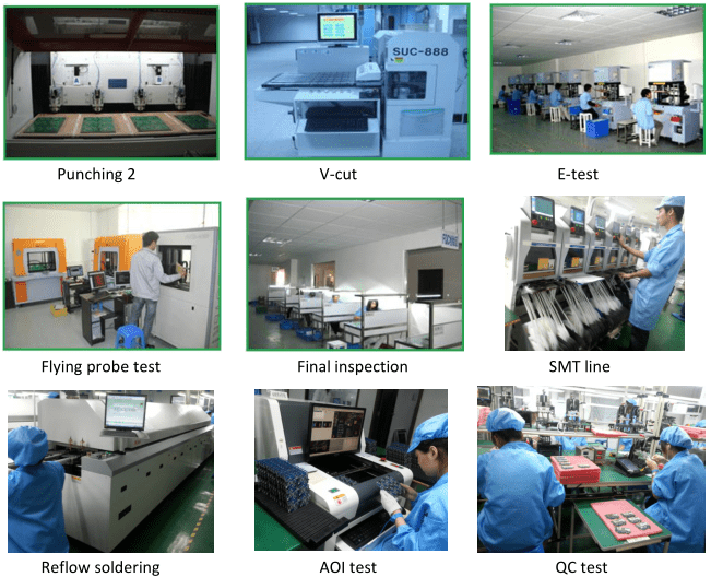
Green Solder Mask: Visually friendly and gentle on the eyes, it reduces fatigue during prolonged use. Widely used in the vast majority of applications—including consumer electronics (such as mobile phones and computer motherboards), industrial equipment, and automotive electronics—it is the industry’s default “standard color.” Green pigments (such as phthalocyanine green) are cost-effective, stable, and highly compatible with epoxy resin, making them suitable for large-scale mass production. The distinct color contrast between the green solder mask and the copper foil (yellow) and substrate (brown) facilitates optical inspection (AOI) and manual identification of circuit details, thereby reducing production errors.
Black solder mask: It conceals the PCB circuit layout, serving to protect design confidentiality. Additionally, its clean and uniform appearance makes it suitable for high-end devices that prioritize aesthetic quality. It is primarily used in high-end electronic products (such as premium smartphones, gaming consoles, and drones), security equipment (concealing circuits to prevent tampering), and custom-branded products (to enhance visual appeal). Black solder mask requires higher manufacturing precision; as it nearly completely covers surface traces, it increases the difficulty of repair and debugging. It demands strict ink uniformity—uneven coating can lead to “white spots” defects. Additionally, due to its high light-absorbing properties, it presents low contrast during AOI inspection, necessitating higher-precision equipment.
Blue solder mask: With a fresh color and excellent visual distinction, it offers a unique visual effect, making it suitable for products seeking differentiation. It is commonly used in communication equipment, instruments, LCD displays, and similar applications, and is also frequently seen in maker or DIY projects (as it facilitates the identification of solder joints during manual soldering). The blue solder mask has good process compatibility and no significant performance shortcomings. It offers good heat resistance, and some blue inks contain titanium, which can improve the reliability of solder joints.
Red Solder Mask: With its vivid color and high visibility, it clearly distinguishes between traces, solid areas, and blank regions, producing an attractive screen-printed finish. It is commonly used in scenarios requiring product line differentiation (such as different modules in home appliances), certain military or medical equipment (where color indicates compliance), and for personalized custom products. The performance of red solder masks is similar to that of green ones, but red pigments are slightly more expensive, and the manufacturing process is relatively complex.
White solder mask: Highly reflective, it enhances the luminous efficiency of light-emitting components such as LEDs. It is commonly used in LED panels (e.g., panel lights, display backlight panels), lighting equipment, and applications requiring reflective assistance (e.g., sensor circuit boards). The color difference between the white solder mask and copper foil (yellow) is minimal, making AOI inspection slightly more challenging and requiring more precise process control during production.
Purple solder mask: Although relatively rare, it offers aesthetic appeal and distinctiveness, making it suitable for applications with specific color requirements.
Special Materials and Substrates
Special materials and substrates play a crucial role in the electronics industry, particularly in high-speed communication and high-frequency signal processing.
With technological advancements, PCBs (printed circuit boards) have evolved beyond simple electrical interconnections to become core components of electronic and communication devices.
The selection of specialty materials directly impacts the performance, stability, and efficiency of the equipment.
Substrate materials for microwave communication are among the key factors; they must possess a stable low dielectric constant (Dk) and a low tangent of loss (tanδ).
These characteristics determine signal transmission loss and speed.
For example, Rogers materials such as RO3003, RO3006, RO3010, RO3203, and RO3210 are all composite materials based on PTFE (polytetrafluoroethylene) and ceramics, offering excellent dielectric and thermal properties.
These materials have varying dielectric constants and tanδ values to meet the requirements of different frequency ranges. For example, RO3003 has a dielectric constant of 3.00, while RO3010 reaches 10.2, making it suitable for higher-frequency applications.
Additionally, the RT/Duroid series, such as 5870, 5880, 6002, 6006, and 6010LM, are also common choices.
RT/Duroid materials are typically composed of PTFE and glass fiber, offering excellent dielectric properties and mechanical strength. For instance, RT/Duroid 5870 has a dielectric constant of 2.33, making it suitable for applications with low loss requirements, while RT/Duroid 6006 has a dielectric constant of 6.15, making it more suitable for high-frequency applications; it also has a higher thermal conductivity, which aids in heat dissipation.
A material’s volume resistivity and surface resistivity are key indicators of its insulation performance, while thermal conductivity determines its heat dissipation capability. For example, Ultralam 2000 has a thermal conductivity of 0.24 W/m·K, making it suitable for high-power modules requiring effective heat dissipation. Moisture absorption is another factor to consider; low moisture absorption minimizes the impact of ambient humidity on material performance.
In addition to the materials listed above, products from other brands such as F4B and Tacnoic are also widely used in the microwave communications field. When selecting substrate materials, designers must conduct a comprehensive evaluation based on specific application requirements—such as signal frequency, power requirements, and environmental conditions—to ensure that the chosen materials meet the device’s performance requirements and guarantee long-term stability.
The selection of specialty materials and substrates is a critical step in the design of electronic and communication equipment, as their performance directly impacts signal transmission quality, power handling capability, and operational lifespan. Understanding the characteristics of various materials and making selections based on actual requirements is the foundation for improving equipment performance and reliability.
The materials are shown in the figure below for reference:
You may also contact our engineering staff directly to discuss processing requirements and manufacturing capabilities.