
Confused about Rogers PCB vs PTFE PCB? Learn the differences between RO4350B, RO4003C, RO3003, RT5880 and other RF materials. Compare dielectric constant, loss tangent, manufacturing processes, frequency ranges, and cost to choose the right high-frequency PCB material for RF, microwave, 5G, radar, satellite communication, and 77GHz automotive radar applications.
Rogers PCB vs PTFE PCB: Understanding the Real Difference
The question “Rogers PCB vs PTFE PCB” appears frequently in RF and microwave design discussions. However, the comparison itself is based on a common misconception.
Rogers PCB is not a single material category. Rogers Corporation manufactures both hydrocarbon ceramic laminates and PTFE-based laminates. Therefore, asking “Rogers vs PTFE” is similar to asking “Toyota vs Electric Vehicle”—some Toyota models are electric.
The meaningful comparison is:
Rogers Hydrocarbon Materials (RO4350B, RO4003C)
PTFE-Based Materials (RO3003, RT5880, Taconic TLY-5, F4B Series)
These material families differ significantly in:
Dielectric properties
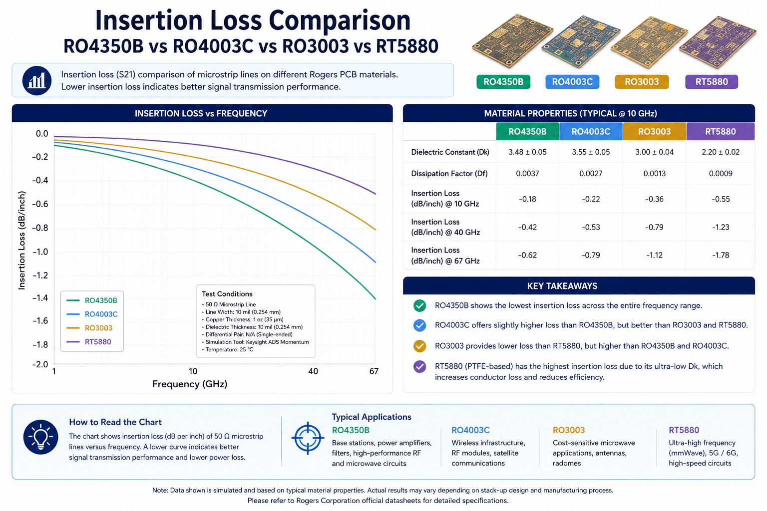
Insertion loss
Manufacturing requirements
Frequency capability
Cost
Factory availability
Understanding these differences helps engineers select the correct material and ensures the chosen PCB manufacturer can reliably fabricate the design.
Quick Summary: Rogers Hydrocarbon vs PTFE PCB
Rogers Hydrocarbon vs PTFE PCB Selection Table
| Application Requirement | Recommended Material |
|---|---|
| 5G Sub-6 GHz Base Station | RO4350B |
| WiFi 6 / WiFi 7 Modules | RO4350B |
| S-Band Radar | RO4350B |
| X-Band Radar | RO4003C |
| Ku-Band VSAT | RO4003C / RO3003 |
| Ka-Band SATCOM | RO3003 |
| 77GHz Automotive Radar | RO3003G2 |
| Electronic Warfare (2–18 GHz) | RT5880 |
| SIGINT Systems | RT5880 |
| W-Band (75–110 GHz) | RT5880 |
| Cost-Sensitive RF Design | RO4350B |
| Lowest Possible Insertion Loss | RT5880 |
Key Takeaway
For most RF applications below 10 GHz, RO4350B provides the best balance between performance, manufacturability, and cost.
For Ka-band, W-band, electronic warfare systems, and ultra-low-loss microwave applications, PTFE materials such as RO3003 and RT5880 become the preferred solution.
The Fundamental Misconception: What Does Rogers PCB Actually Mean?
Many engineers use the term “Rogers PCB” to describe any PCB manufactured using Rogers materials.
In reality, Rogers materials fall into two distinct categories:
Rogers Hydrocarbon Ceramic Materials
The RO4000 Series was specifically developed to deliver RF performance while maintaining compatibility with standard FR4 manufacturing processes.
Rogers RO4350B
Dk: 3.48 ±0.05 @10 GHz
Df: 0.0037 @10 GHz
Tg: >280°C
FR4-compatible processing
Widely available
Rogers RO4003C
Dk: 3.38 ±0.05 @10 GHz
Df: 0.0027 @10 GHz
Tg: >280°C
FR4-compatible processing
Lower loss than RO4350B
Advantages:
Standard FR4 fabrication equipment
No PTFE activation process
Easier multilayer construction
Lower manufacturing cost
Rogers PTFE Materials
PTFE materials offer lower insertion loss but require specialized fabrication processes.
Rogers RO3003
Dk: 3.00 ±0.04
Df: 0.0010
Excellent dimensional stability
Ideal for Ka-band and 77 GHz radar
Rogers RT5880
Dk: 2.20 ±0.02
Df: 0.0009
Ultra-low loss
Ideal for EW and W-band applications
Advantages:
Lowest insertion loss
Superior microwave performance
Better phase stability
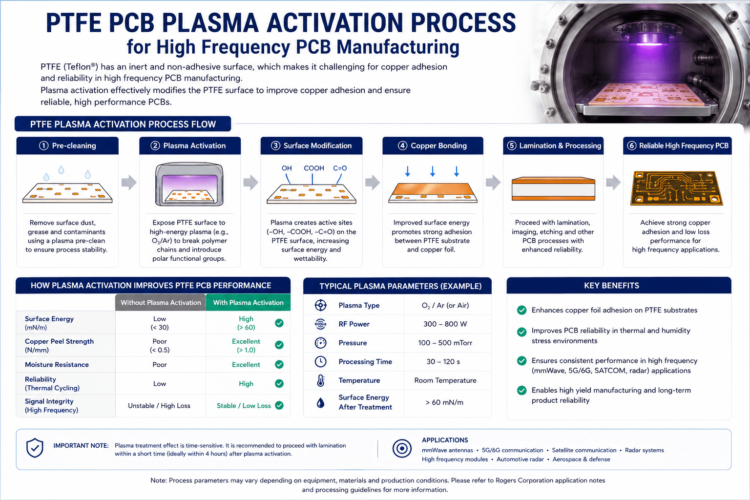
Challenges:
Plasma activation required
PTFE-specific drilling
Specialized lamination process
Higher manufacturing cost
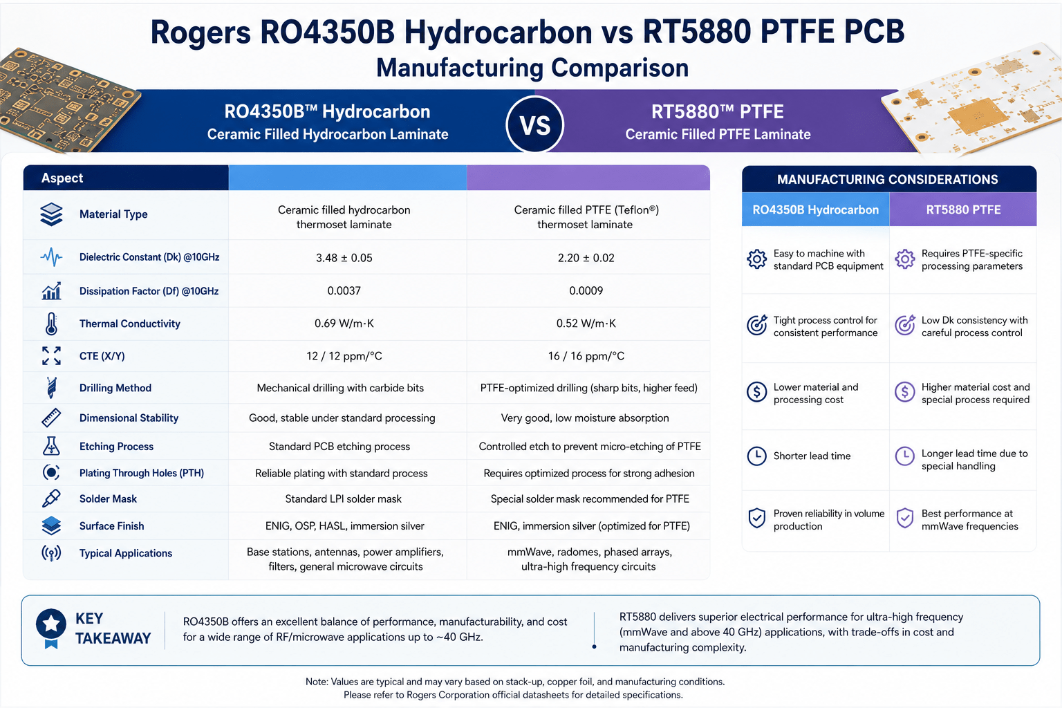
Rogers Hydrocarbon vs PTFE: Complete Material Comparison
| Property | RO4350B | RO4003C | RO3003 | RT5880 |
|---|---|---|---|---|
| Material Type | Hydrocarbon Ceramic | Hydrocarbon Ceramic | PTFE Ceramic | PTFE Glass |
| Dk @10GHz | 3.48 | 3.38 | 3.00 | 2.20 |
| Df @10GHz | 0.0037 | 0.0027 | 0.0010 | 0.0009 |
| Tg | >280°C | >280°C | PTFE | PTFE |
| Hole Wall Activation | No | No | Yes | Yes |
| Manufacturing Complexity | Low | Low | High | High |
| Cost | Moderate | Moderate | High | High |
| Typical Frequency | Up to X-Band | Up to Ku-Band | Ka-Band | W-Band |
When to Choose Rogers Hydrocarbon Materials
Applications Below 8 GHz
RO4350B is typically the best choice for:
5G Sub-6 GHz
WiFi 6 and WiFi 7
L-Band Communications
S-Band Radar
VSAT Systems
Benefits include:
Lower manufacturing cost
Wide factory availability
Reliable multilayer construction
When to Choose PTFE PCB Materials
Applications Above 26.5 GHz
PTFE becomes necessary when insertion loss budgets become critical.
Recommended applications:
RO3003
Ka-Band Radar
Ka-Band SATCOM
77 GHz Automotive Radar
Missile Seekers
High-Performance Phased Arrays
RT5880
Electronic Warfare Systems
SIGINT Platforms
Wideband Receivers
W-Band Sensors
Aerospace Microwave Systems
Manufacturing Differences: Hydrocarbon vs PTFE
RO4350B / RO4003C Processing
Standard FR4 drilling
Standard desmear process
RO4450F bonding film
Up to 3 lamination cycles
Most RF PCB factories can process RO4350B successfully.
RO3003 / RT5880 Processing
PTFE-specific drilling parameters
Plasma activation or sodium naphthalene treatment
Rogers 2929 bondply
Maximum 2 lamination cycles
Not all PCB factories possess PTFE processing capability.
Verification Question
Ask the factory:
“What hole wall activation method do you use for PTFE materials?”
Qualified answers:
Plasma activation
Sodium naphthalene activation
Vague answers often indicate limited PTFE manufacturing experience.
Cost Comparison
Approximate relative cost ranking:
RO4350B
RO4003C
RO3003
RT5880
PTFE materials typically increase total PCB cost by:
30%–80%
depending on layer count, thickness, and fabrication complexity.
Cost alone should not determine material selection.
The correct choice depends on:
Frequency
Insertion loss budget
System performance requirements
Hybrid Stackups: Combining PTFE and FR4
Many advanced RF systems combine PTFE RF layers with FR4 digital layers.
Examples:
RO3003 + FR4
RT5880 + FR4
RO4350B + FR4
Benefits:
Reduced cost
Improved RF performance
Better overall system optimization
Design considerations include:
Bondply selection
CTE matching
Warpage control
Lamination cycle limits
Why Choose SZXCEPCB for Rogers and PTFE PCB Manufacturing?
SZXCEPCB specializes in high-frequency PCB fabrication for:
RF Communication
Microwave Systems
Satellite Communication
Automotive Radar
Aerospace Electronics
Defense Applications
Capabilities include:
RO4350B PCB
RO4003C PCB
RO3003 PCB
RO3006 PCB
RO3010 PCB
RT5880 PCB
Taconic TLY-5
Taconic TLP-5
F4B Series PTFE Materials
Hybrid Rogers + FR4 Stackups
Controlled Impedance Testing
IPC Class 2 and IPC Class 3 Manufacturing
Request a Quote
Need help selecting between RO4350B, RO3003, and RT5880?
Send the following information to SZXCEPCB:
- Gerber Files
- Layer Stackup
- Operating Frequency
- PCB Thickness
- Copper Weight
- Impedance Requirements
- Quantity
Our engineering team will recommend the most suitable material and manufacturing process for your project.