
Dk 3.48 · Df 0.0037 · UL 94 V-0 · processes exactly like FR-4 — the default production laminate for mid-band RF, explained by the factory that machines it.
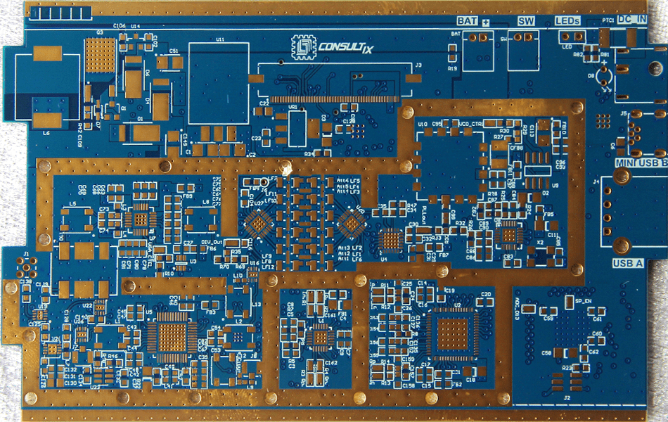
What Is Rogers RT/duroid® 4350B?
Bottom line up front: Rogers RO4350B (part of the RT/duroid®/RO4000® family) is a hydrocarbon-ceramic laminate with a dielectric constant of 3.48 and a dissipation factor of 0.0037 at 10 GHz. It delivers most of the RF performance of premium PTFE materials while processing exactly like FR-4 — which makes it the most cost-effective choice for mid-band RF production.
A common misconception: RO4350B is not a PTFE material. It uses a proprietary thermoset resin system filled with ceramic, which is precisely why standard PCB fabricators can process it without the special hole preparation and handling that PTFE laminates require. (The PTFE material in Rogers’ portfolio is RT/duroid® 5880 — see our dedicated 5880 guide.)
The laminate is supplied copper-clad in multiple dielectric thicknesses and copper weights, and it carries a UL 94 V-0 flame retardant rating — rare among high-frequency laminates and often mandatory for commercial products.
Key Specifications at a Glance
The numbers that define RO4350B in a stackup review:
| Property | Typical Value |
|---|---|
| Dielectric constant (Dk) @ 10 GHz | 3.48 ± 0.05 |
| Dissipation factor (Df) @ 10 GHz | 0.0037 |
| Resin system | Hydrocarbon / ceramic (thermoset), not PTFE |
| Glass transition (Tg) | > 280°C |
| Flame rating | UL 94 V-0 |
| Processing | Standard FR-4 process |
5 Key Advantages of RO4350B
1. Processes Exactly Like FR-4
This is the material’s defining advantage. Unlike PTFE laminates, RO4350B needs no special drilling parameters, no sodium etch preparation for plated through-holes, and no exotic lamination profiles. For buyers this translates into lower fabrication cost, more supplier options, and faster lead times.
2. Tight Dielectric Constant Tolerance
With Dk held to 3.48 ± 0.05, impedance calculations stay predictable from design to production. For antennas, filters, and power amplifiers where return loss matters, this tight tolerance directly improves first-pass design success.
3. Low Loss Where It Counts
A dissipation factor of 0.0037 at 10 GHz is roughly five times better than standard FR-4. For circuits in the 1–20 GHz range — GPS, cellular bands, 24 GHz radar — RO4350B cuts insertion loss dramatically without jumping to premium PTFE pricing.
4. Excellent Thermal and Mechanical Reliability
A glass transition temperature above 280°C and low Z-axis coefficient of thermal expansion keep plated vias reliable through lead-free reflow assemblies. Combined with the UL 94 V-0 rating, RO4350B meets the reliability and safety requirements of commercial and automotive programs.
5. Straightforward Multilayer Construction
RO4350B bonds well with standard prepreg systems and hybridizes cleanly with FR-4 layers. Multilayer RF boards — for example a 4-layer board with two RF layers — are a routine, repeatable build on any well-run FR-4 line.
Typical Applications
Automotive Radar and Telematics
RO4350B is widely used in 24 GHz and 77 GHz radar sensor boards, where its thermal reliability and flame rating meet automotive qualification demands.
Power Amplifiers and RF Front-Ends
Good thermal conductivity and low loss make it a workhorse for LNA/PA boards, diplexers, and front-end modules in cellular infrastructure.
Antennas and Passive Networks
Patch antennas, arrays, couplers, and filters benefit from the tight Dk tolerance and predictable behavior across production lots.
Medical and Industrial Wireless
Wireless monitoring devices and industrial sensors use RO4350B where V-0 flammability and stable RF performance are both required.
RO4350B vs RT/duroid® 5880 vs FR-4
How the three most-requested materials compare in our quoting work:
| RO4350B | RT/duroid® 5880 | FR-4 | |
|---|---|---|---|
| Dk @ 10 GHz | 3.48 | 2.20 | ~4.2–4.6 |
| Df @ 10 GHz | 0.0037 | 0.0009 | ~0.02 |
| Resin system | Hydrocarbon / ceramic | PTFE | Epoxy |
| Processing | Standard FR-4 process | PTFE-experienced fab required | Standard |
| Relative cost | Mid | Premium | Low |
Rule of thumb: RO4350B for mid-band RF production where cost matters; 5880 for millimeter-wave and lowest-loss designs; FR-4 for digital and low-frequency work.
Manufacturing Considerations for RO4350B
RO4350B is forgiving, but a few points still decide board quality:
- Impedance control: we hold ±10% tolerance with coupon verification; the tight laminate Dk tolerance makes this much easier than on FR-4.
- Hybrid stackups: pairing RO4350B RF layers with FR-4 cores controls cost on multilayer designs; lamination ramp profiles need attention to manage CTE mismatch.
- Copper selection: standard ED foil works for most builds; rolled foil improves conductor loss on critical analog lines.
- Surface finish: ENIG is the default for RF pads and wire-bondable areas.
XCE PCB manufactures RO4350B boards from 2 to 72 layers, panel sizes up to 600×1200 mm, with prototype builds in as fast as 24 hours to IPC-A-600G criteria.
Why Choose XCE PCB for RO4350B Boards
XCE PCB (Xinchenger Electronics) is a Shenzhen high-frequency PCB manufacturer operating since 2009 — 5,000 m² factory, 80+ engineers, 10,000+ completed projects. We fabricate the full high-frequency laminate range — Rogers RO4000® and RT/duroid® series, Taconic, Arlon, and domestic F4B — under one quality system.
Material sourcing, impedance engineering, and fabrication are all in-house, so you have one accountable partner from Gerber review to shipment.
Conclusion
RO4350B earns its place as the default production laminate for mid-band RF: Dk 3.48 with tight tolerance, five times lower loss than FR-4, V-0 flame rating, and — uniquely among high-frequency materials — standard FR-4 processing. That combination is why it appears in everything from automotive radar to base station amplifiers. If you are deciding between RO4350B and a PTFE option, send us your stackup; our engineers will review impedance, cost, and manufacturability before you commit.
Frequently Asked Questions
Is Rogers RO4350B a PTFE material?
What is the dielectric constant of RO4350B?
Can RO4350B be used for multilayer PCBs?
Is RO4350B suitable for 77 GHz automotive radar?
How fast can you deliver RO4350B prototypes?
Need Rogers RO4350B PCBs?
Send us your Gerber files and requirements for a manufacturability review and a tailored quotation.
sales1@xcepcb.com
+86 180 3818 8537