Rogers PCB materials guide covering RO4350B, RO4003C, RO3003, RT5880, RT5870, RO3006, RO3010 and RO6010. Compare dielectric constant, loss tangent, applications, manufacturing capabilities, and hybrid Rogers PCB solutions for RF, microwave, radar, satellite, and 5G communication systems.
Rogers PCB Materials Guide: RO4350B, RO4003C, RO3003, RT5880 Specifications and Manufacturing Capabilities
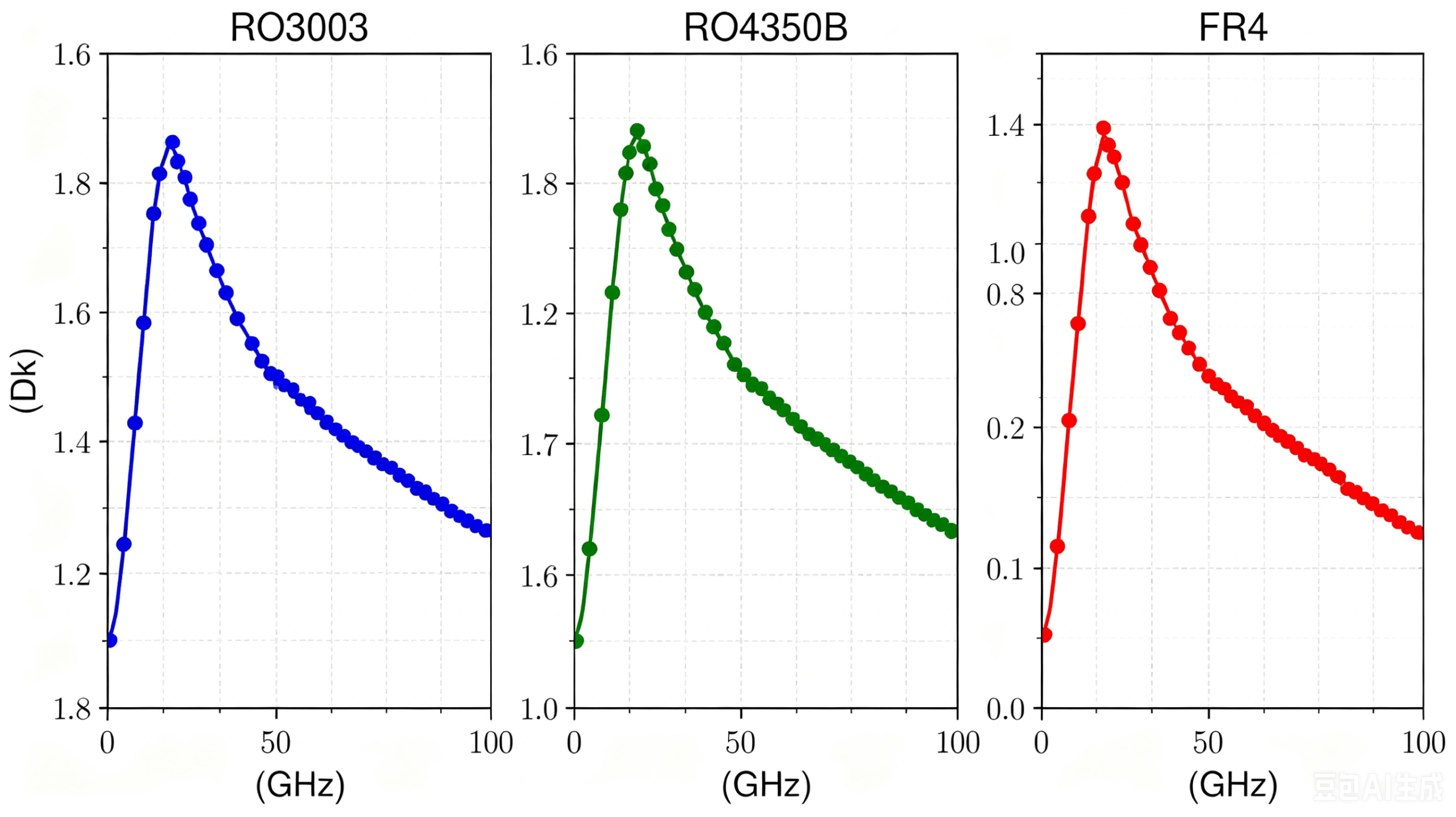
Rogers PCB materials are widely used in RF, microwave, radar, satellite communication, aerospace, automotive radar, and 5G infrastructure applications where conventional FR4 materials cannot meet signal integrity and insertion loss requirements. Selecting the right Rogers laminate is critical because dielectric constant (Dk), dissipation factor (Df), thermal stability, and manufacturing processes directly affect system performance.
At SZXCEPCB, we maintain regular inventory of Rogers RO4350B, RO4003C, RO3003, RT5880, RT5870, RO3006, RO3010, and RO6010 materials. We support both standard Rogers fabrication and hybrid Rogers + FR4 stackups for customers seeking an optimal balance between RF performance and manufacturing cost.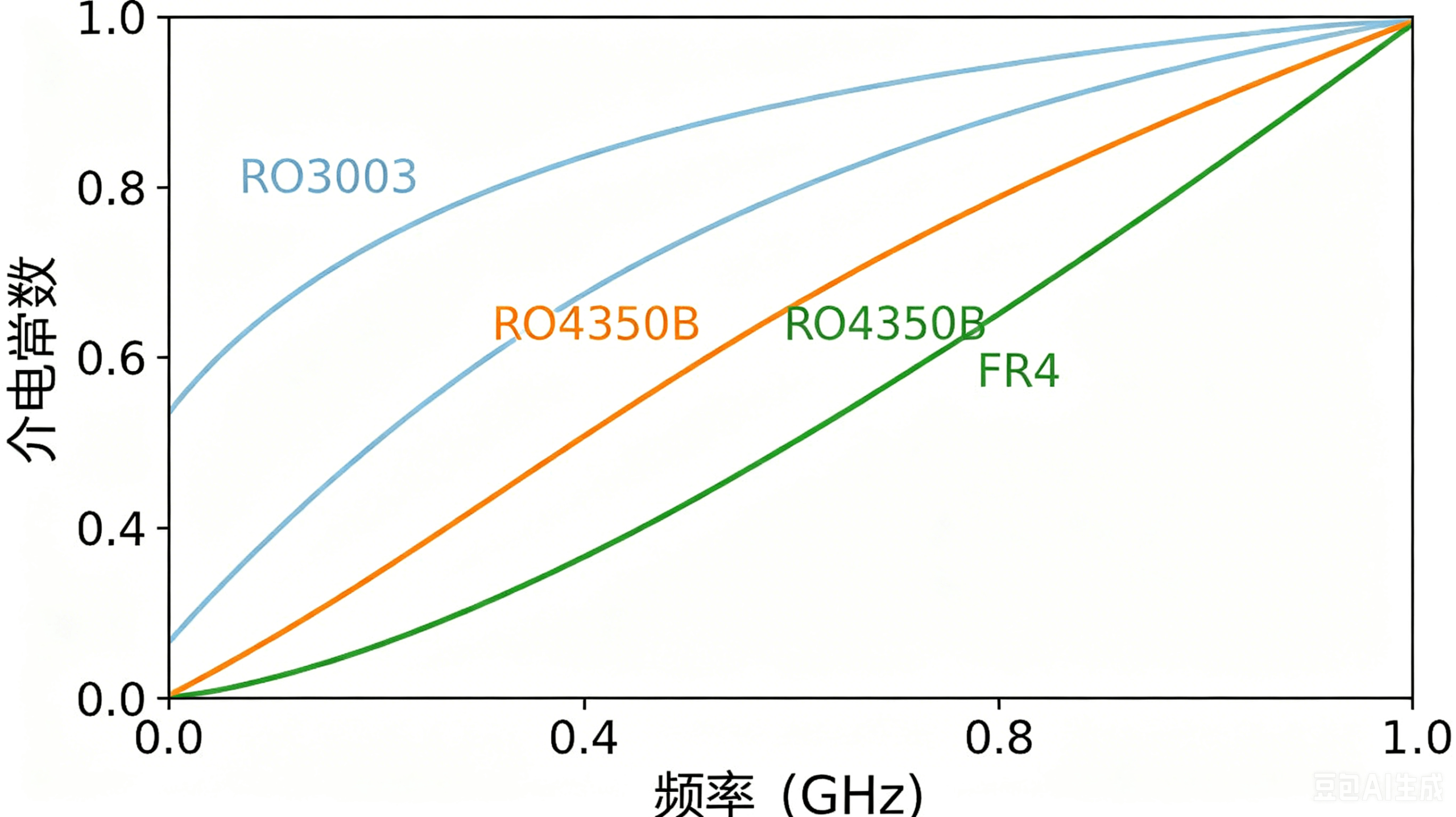
Rogers RO4350B, RO4003C, RO3003 and RT5880 high-frequency PCB materials
Rogers PCB materials including RO4350B RO4003C RO3003 and RT5880
Quick Overview of Rogers PCB Materials
Rogers Corporation manufactures several high-frequency laminate families designed for different RF and microwave applications.
The most commonly used material groups include:
RO4000 Series
RO4350B and RO4003C belong to the RO4000 hydrocarbon ceramic family. These materials are designed to process similarly to FR4 while delivering significantly lower dielectric loss.
Advantages include:
FR4-compatible processing
Excellent dimensional stability
Lower manufacturing cost than PTFE materials
Suitable for multilayer PCB designs
No plasma hole-wall activation required
RO3000 Series
RO3003, RO3006, and RO3010 are PTFE ceramic laminates offering lower insertion loss and excellent electrical stability across wide frequency ranges.
Advantages include:
Low dielectric loss
Excellent microwave performance
Stable dielectric constant
Suitable for Ka-band and millimeter-wave designs
RT/Duroid Series
RT5880 and RT5870 are among the most recognized PTFE-based RF materials in the industry.
Applications include:
Aerospace electronics
Military radar systems
Satellite communication
Electronic warfare systems
High-frequency antenna networks
For official material specifications, visit Rogers Corporation:
https://rogerscorp.com
Rogers PCB Materials Available
Current stocked materials include:
RO4350B
RO4003C
RO3003
RO3006
RO3010
RT5880
RT5870
RO6010
Supported constructions:
Single-sided Rogers PCB
Double-sided Rogers PCB
Multilayer Rogers PCB
Rogers + FR4 Hybrid PCB
Controlled impedance PCB
For customers evaluating hybrid stackups, see our relatedguide:https://szxcepcb.com/category/about-pcb/
Material Specifications Reference
| Material | Dk | Df | Type | Typical Application |
|---|---|---|---|---|
| RO4350B | 3.48 | 0.0037 | Hydrocarbon Ceramic | 5G antennas, RF amplifiers |
| RO4003C | 3.38 | 0.0027 | Hydrocarbon Ceramic | RF communication modules |
| RO3003 | 3.00 | 0.0010 | PTFE Ceramic | Automotive radar |
| RO3006 | 6.15 | 0.0020 | PTFE Ceramic | Compact RF circuits |
| RO3010 | 10.2 | 0.0022 | PTFE Ceramic | Filters and couplers |
| RT5880 | 2.20 | 0.0009 | PTFE Glass | Aerospace and radar |
| RT5870 | 2.33 | 0.0012 | PTFE Glass | Microwave communication |
| RO6010 | 10.2 | 0.0023 | Ceramic PTFE | High-Dk microwave designs |
Why Engineers Choose Rogers PCB Materials
The primary reason engineers specify Rogers PCB materials is electrical performance.
Compared with conventional FR4:
Lower insertion loss
Better impedance control
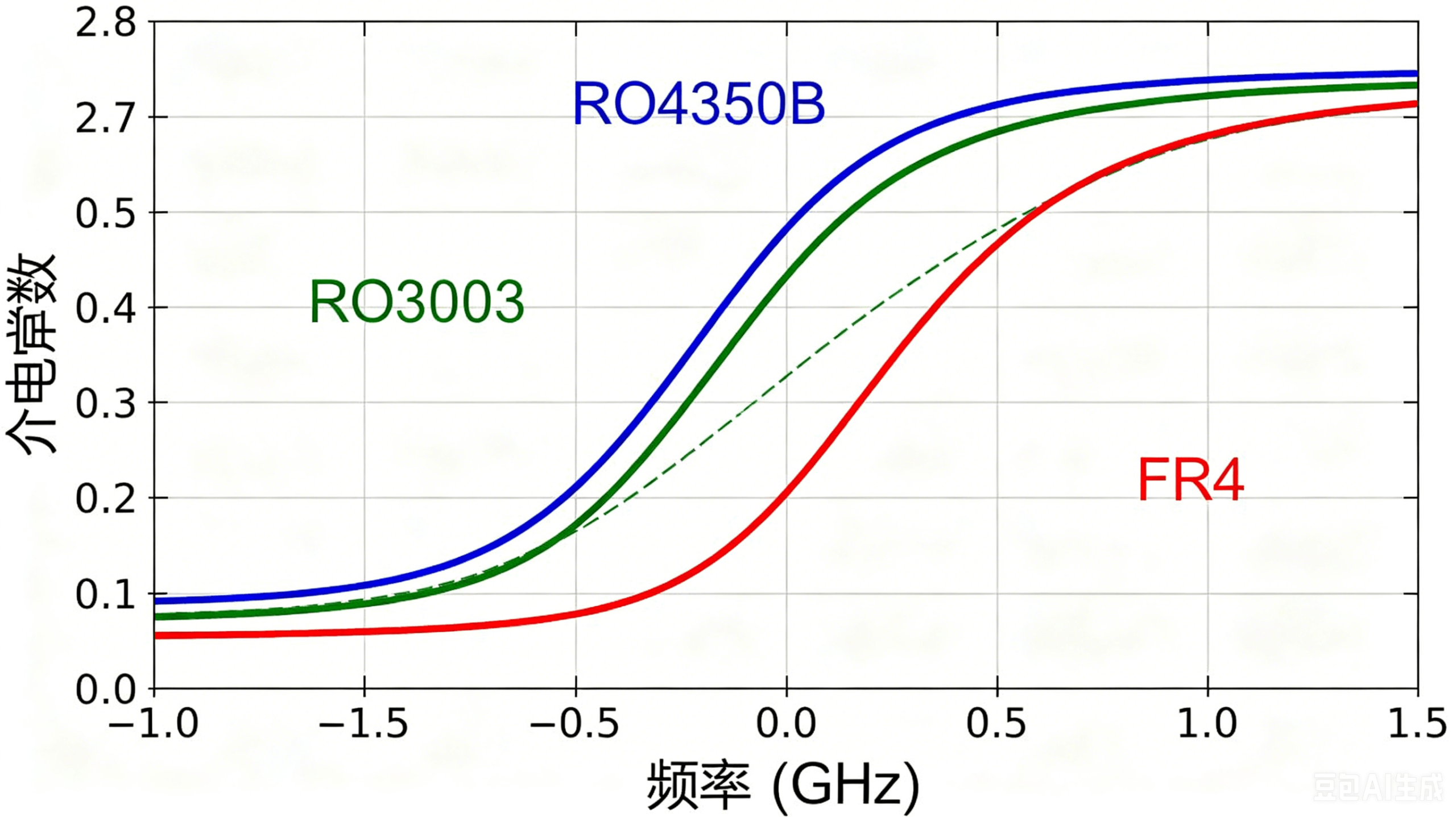
More stable dielectric properties
Improved phase consistency
Better performance above 1 GHz
As operating frequencies increase, material selection becomes increasingly important.
A standard FR4 laminate may have a dissipation factor around 0.020.
RT5880 offers a dissipation factor of only 0.0009.
This significant difference can dramatically reduce insertion loss in long RF transmission paths.

Manufacturing Capabilities
Not all Rogers materials are manufactured using the same process.
RO4000 Series Processing
RO4350B and RO4003C can be processed using equipment similar to standard FR4 production.
Characteristics:
Standard drilling process
Standard desmear process
Conventional multilayer lamination
Rogers RO4450F bondply supported
PTFE Material Processing
RO3003, RO3006, RO3010, RT5880, and RT5870 require specialized manufacturing techniques.
These include:
PTFE-specific drilling parameters
Plasma hole-wall activation
Specialized lamination profiles
Strict process control
At SZXCEPCB, all PTFE materials undergo in-house plasma activation before copper deposition to ensure reliable plated through-hole performance.
For more information about PTFE PCB manufacturing:
Internal Link:
https://szxcepcb.com/category/about-pcb/
Applications of Rogers PCB Materials
Different Rogers materials are optimized for different applications.
RO4350B
Typical applications:
5G base stations
RF amplifiers
Wireless communication modules
Industrial RF systems
RO4003C
Typical applications:
RF filters
Power amplifiers
Satellite communication equipment
RO3003
Typical applications:
Automotive radar
Millimeter-wave systems
Satellite communication
RT5880
Typical applications:
Aerospace electronics
Military radar
Electronic warfare systems
High-performance antenna arrays
Rogers PCB vs FR4
Many customers ask whether Rogers material is always necessary.
The answer depends on operating frequency.
General guideline:
Below 500 MHz: FR4 is often sufficient
1 GHz–10 GHz: RO4350B or RO4003C recommended
Above 20 GHz: PTFE materials become increasingly important
Ka-band and millimeter-wave: RO3003 or RT5880 preferred
For detailed RF material selection guidance, engineers can also refer to:
https://www.microwavejournal.com
and
Why Choose SZXCEPCB
We specialize in high-frequency PCB manufacturing for RF and microwave applications.
Capabilities include:
Rogers PCB fabrication
PTFE PCB fabrication
Hybrid Rogers + FR4 PCB
Controlled impedance testing
TDR verification
IPC Class 2 manufacturing
IPC Class 3 manufacturing
Prototype and production volumes
Lead time:
Prototype: 5–7 working days
No MOQ requirement
Engineering review support includes:
Material selection
Stackup design
Impedance calculation
Manufacturing feasibility analysis
Cost optimization recommendations
Related Resources
RO4350B PCB Manufacturing Guide:
https://szxcepcb.com
RT5880 PCB Fabrication:
https://szxcepcb.com/product/rogers-5880-gold-plated-pcb/
High Frequency PCB Manufacturing:
https://szxcepcb.com/inventory/page/2/