
Satellite payloads and 5G base stations impose the same three demands on a laminate — a defensible loss budget, channel-to-channel phase consistency, and dimensional survival of the environment — but they answer them with different Taconic grades. This guide maps each demand to the material lines that actually carry it, with datasheet numbers throughout.
Demand 1 — The Loss Budget
Every dB spent in the laminate is a dB not spent on range, link margin or power amplifier efficiency. Here the ultra-low-loss grades lead: TLY-5 measures Df 0.0009 at 10 GHz with Dk 2.20 ±0.02 — roughly 20× lower dielectric loss than FR-4 — which is why it anchors LNA front ends, long feed networks and wideband antenna elements. Where the design needs rigidity more than the last tenth of a dB, the TLX family holds Df ≈0.0019 with woven-glass stiffness. For PA and coupler work, RF-35 (Dk 3.50 ±0.05, Df 0.0018 at 10 GHz, Tg above 315 °C) carries power with FR-4-like processability.
Demand 2 — Phase Consistency Across the Array
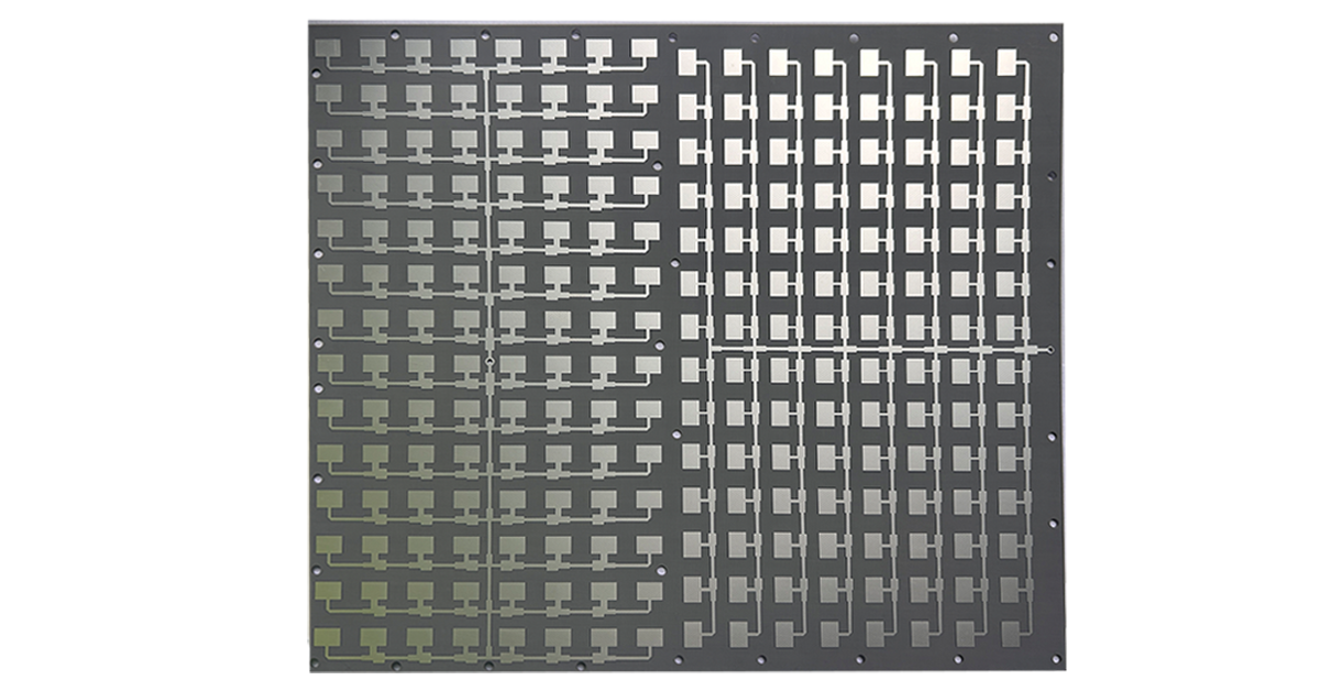
Beamforming is arithmetic on phase, and phase errors start in the laminate. Two Taconic behaviors matter: tight Dk tolerance (TLY-5 ±0.02, TLX and TMS-DS3 ±0.04), so every channel sees the same effective dielectric; and low dispersion, so channels at different frequencies inside a wideband array stay matched — TMS-DS3 drifts only from 3.00 at 1 GHz to 3.02 at 40 GHz. Temperature adds the second axis: TMS-DS3 holds Dk within ±0.25% from −30 to +120 °C, keeping outdoor and orbital thermal swings from re-phasing the array.
Demand 3 — Surviving the Environment
- Outgassing for orbit. TLY-5’s datasheet references NASA outgassing measurements of TML/CVCM/WVR at 0.01/0.01/0.01% — the volatile release data space programs screen against. Note this is datasheet test data, not a blanket “NASA certification”: qualification is always per program.
- Thermal cycling through thickness. PTFE laminates still expand 130–217 ppm/°C on the Z axis, which stresses plated holes through repeated orbital cycles. TLY-5Z — a ceramic-filled, woven-glass variant — cuts Z-CTE to 130 ppm/°C at density 1.92 g/cm³ with Df 0.0015, the standard exit when PTH reliability dominates.
- Moisture. Sub-0.02–0.03% absorption across the family keeps ground-station and marine-terminal impedance where the design left it.
The Material Map for Satellite and 5G Hardware
| Grade | Key numbers | Role |
|---|---|---|
| TLY-5 | Dk 2.20 ±0.02 / Df 0.0009 @10GHz | Lowest-loss paths: feeds, front ends, mmWave antennas |
| TLY-5Z | Dk 2.20 ±0.04 / Df 0.0015 / Z-CTE 130 | Multilayer satellite boards needing PTH reliability |
| TLX family | Dk 2.45–2.65 ±0.04 / Df ≈0.0019 | Rigid 5G antennas, arrays, test equipment |
| RF-35 | Dk 3.50 ±0.05 / Df 0.0018 @10GHz / Tg>315°C | Power amplifiers, couplers, filters |
| RF-10 | Dk 10.2 ±0.3 / Df 0.0025 @10GHz | GNSS/patch antennas where size dominates |
| TMS-DS3 | Dk 3.00 ±0.04 / Df 0.0011 / 0.65 W/m·K | High-power T/R modules, phased-array manifolds |
| NF-30 | Dk ≈3.0 @78GHz measured / non-reinforced | 77–79 GHz automotive radar sensors |
Satellite Applications in Practice
GNSS and patch antennas run on high-Dk RF-10: Dk 10.2 shrinks a patch to roughly a third of the linear size it would need on 2.2-class material, at Df 0.0025 and thermal conductivity 0.85 W/m·K (unclad) — the standard recipe for navigation terminals and aircraft collision-avoidance antennas. Payload and bus RF leans on TLY-5 for receive paths and TMS-DS3 where power amplifier stages sit. Ground stations favor TLX for its rigidity over large panels. The orbit-environment engineering (outgassing, thermal cycling, Z-axis rules) parallels what satellite-grade Rogers 5880 boards face — see the satellite machining analysis.
5G Applications in Practice
Massive MIMO antennas demand the phase discipline of sec-2: TLX and TLY-5 keep element feeds consistent across hundreds of channels. mmWave small cells and backhaul push into 24–40 GHz, where the TLX loss step and copper roughness both enter the budget — TLY-5 is the usual upgrade when the link is marginal. Base station PA pallets take RF-35; its Tg above 315 °C survives lead-free assembly without argument. High-speed digital companion fabrications (fronthaul/baseband boards) use Taconic’s fastRise line rather than RF laminates — different chemistry, different selection logic.
Building Satellite and 5G Boards With XCE PCB
XCE PCB fabricates Taconic boards on a PTFE-capable line: 2–72 layers, impedance ±10%, panels to 600 × 1200 mm, samples in as fast as 24 hours with laminate in stock. For the family context, start at the Taconic properties overview and the laminate family guide; the TLY-5 deep dive is here.
Frequently Asked Questions
Which Taconic laminate is best for satellite communication PCBs?
Is Taconic TLY-5 certified by NASA?
Why is Dk tolerance so important for 5G Massive MIMO?
What is the difference between TLY-5 and TLY-5Z?
Which material handles power amplifier stages?
Quoting a Satellite or 5G Build?
Send us your Gerber files and requirements for a manufacturability review and a tailored quotation.
sales1@xcepcb.com
+86 180 3341 4657