
Dk 2.90–3.00 · Df < 0.0018 · 300°C thermal stability — the balanced PTFE laminate behind communication, radar, medical, and aerospace RF designs.
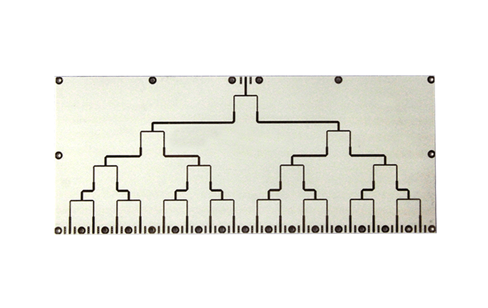
RT/duroid® 3010: The Short Answer
Bottom line up front: Rogers RT/duroid® 3010 is a PTFE-based laminate with inorganic fillers that combines a moderate dielectric constant (2.90–3.00), very low loss (Df below 0.0018), and thermal stability up to 300°C. It performs stably from several gigahertz to tens of gigahertz, which makes it a workhorse for communication equipment, radar, medical devices, and aerospace electronics.
Below is what our production team sees as the material’s unique advantages — electrical, thermal, mechanical, and environmental — and where it fits best.
Composition and Structure
RT/duroid® 3010 is built on a polytetrafluoroethylene (PTFE) matrix mixed with inorganic fillers. The division of labor is deliberate: PTFE provides insulation and chemical resistance, while the inorganic fillers enhance mechanical strength and thermal stability.
The optimized microstructure minimizes signal loss during transmission, improving signal stability and reliability at high frequencies — the reason the laminate holds its electrical numbers consistently from panel to panel.
Electrical Performance
The numbers that define the material:
| Property | Value | What it means for your design |
|---|---|---|
| Dielectric constant (Dk) | 2.90 – 3.00 | Reduces signal attenuation; supports compact transmission-line geometry |
| Dissipation factor (Df) | < 0.0018 | Low loss preserves signal integrity at high frequency |
| Frequency stability | Stable from several GHz to tens of GHz | One laminate across communication, radar, and RF device bands |
| Thermal weight-loss temperature | Up to 300°C | Stable long-term operation in high-temperature, high-power builds |
| Thermal conductivity | Relatively high | Faster heat dissipation, longer equipment life |
| Composition | PTFE matrix + inorganic fillers | Insulation and chemical resistance plus mechanical strength |
Dk of 2.90–3.00 sits in the practical middle ground: low enough to reduce signal attenuation and shrink transmission-line dimensions, high enough to keep fine geometry manageable. Df below 0.0018 is what secures signal integrity in demanding high-frequency transmission.
Thermal Performance
Thermal stability: a thermal weight-loss temperature up to 300°C allows stable long-term operation in high-temperature environments — the requirement behind power amplifiers and RF components that run hot.
Thermal conductivity: relatively high for an RF laminate, aiding rapid heat dissipation and reducing overheating risk. In high-power applications this directly extends equipment lifespan.
Mechanical Performance and Machinability
RT/duroid® 3010 exhibits superior mechanical strength and toughness, withstanding significant mechanical stress in complex circuit designs. Just as important at the factory: it is easy to process, supporting laser cutting and precision machining — which lets designers push more complex layouts and miniaturized geometries without fighting the material.
Environmental Adaptability
Two properties make 3010 dependable in the field:
- Chemical stability: good resistance to various chemicals, ensuring long-term reliability in harsh industrial conditions.
- Humidity resistance: excellent moisture resistance keeps electrical performance stable in humid environments — critical for equipment that must operate through variable conditions.
Where RT/duroid® 3010 Is Used
From our order book, four fields dominate:
| Application area | Typical uses | Why 3010 fits |
|---|---|---|
| Communication equipment | Base stations, satellite communications, radio devices | High-quality signal transmission at RF bands |
| Radar systems | Military and civilian radar | High-frequency stability and low loss |
| Medical devices | Imaging and monitoring equipment | Stringent signal stability requirements |
| Aerospace | Spacecraft and avionics | Reliability and stability in demanding conditions |
The common thread: applications that need stable, low-loss RF performance over long service life and cannot tolerate electrical drift.
Manufacturing Considerations at XCE PCB
Like all PTFE-based laminates, 3010 rewards a fabricator with dedicated process controls — drilling, desmear, and lamination parameters tuned for PTFE rather than standard FR-4. We hold impedance to ±10% with coupon verification on every panel.
XCE PCB manufactures RT/duroid® 3010 boards from 2 to 72 layers, panels up to 600×1200 mm, with prototypes in as fast as 24 hours to IPC-A-600G criteria.
Conclusion
RT/duroid® 3010’s case is simple: moderate Dk, very low Df, 300°C thermal headroom, strong mechanicals, and proven environmental resistance — a balanced laminate rather than an extreme one. That balance is why it keeps appearing in communication, radar, medical, and aerospace designs. If you are evaluating 3010 for a build, send us your stackup and frequency band; our engineers will review manufacturability and quote with the process plan attached.
Frequently Asked Questions
What is the dielectric constant of Rogers RT/duroid 3010?
Is RT/duroid 3010 suitable for high-power RF designs?
What is the difference between RT/duroid 3010 and 5880?
Does RT/duroid 3010 absorb moisture?
How fast can you build RT/duroid 3010 prototypes?
Evaluating RT/duroid® 3010 for Your Build?
Send us your Gerber files and requirements for a manufacturability review and a tailored quotation.
sales1@xcepcb.com
+86 180 3818 8537