
Dk 2.33 · Df 0.0005 · the lowest-loss laminate in the RT/duroid® family — explained by the factory that machines it every day.
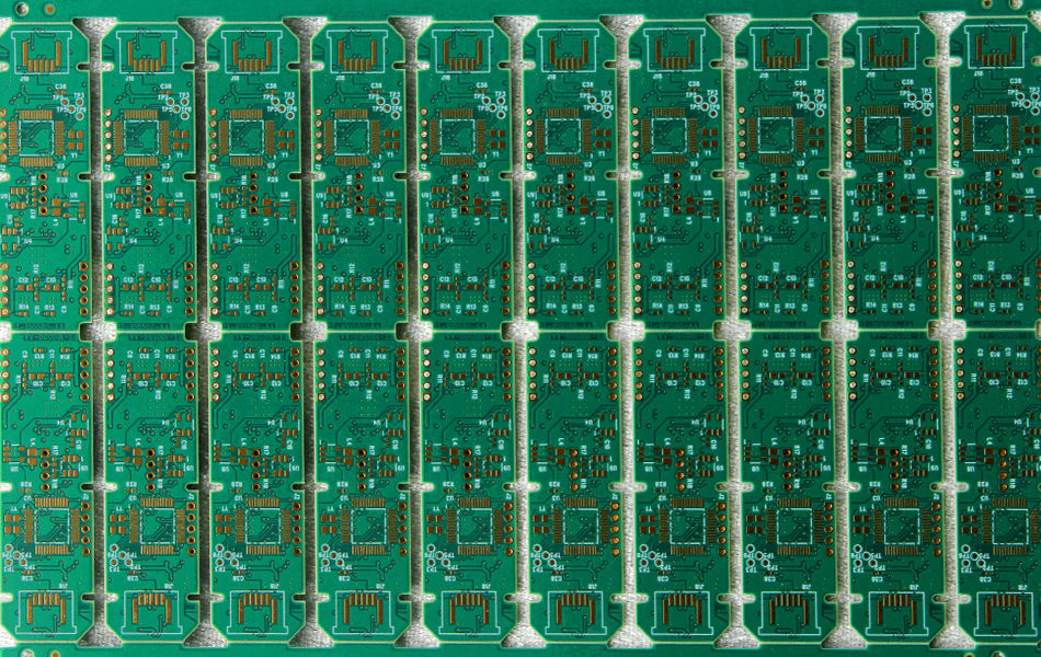
What Is Rogers RT/duroid® 5870?
Bottom line up front: Rogers RT/duroid® 5870 is a PTFE glass-microfiber laminate with a dielectric constant of 2.33 and a dissipation factor as low as 0.0005 at 10 GHz — among the lowest loss values of any commercial PCB material. It is the sibling of RT/duroid® 5880 and the material we reach for when insertion loss, not dielectric constant, is the limiting factor in an RF design.
Like 5880, RT/duroid® 5870 uses randomly oriented glass microfibers in a PTFE matrix, giving it isotropic electrical behavior and highly repeatable etching and machining. The slightly higher dielectric constant compared with 5880 lets designers pack the same impedance into finer line geometries — useful where board real estate is tight.
The laminate is supplied copper-clad in a range of dielectric thicknesses with electrodeposited or rolled-annealed copper foil.
Key Specifications at a Glance
The defining numbers of RT/duroid® 5870:
| Property | Typical Value |
|---|---|
| Dielectric constant (Dk) @ 10 GHz | 2.33 |
| Dissipation factor (Df) @ 10 GHz | 0.0005 |
| Base material | PTFE, glass microfiber reinforced |
| Moisture absorption | Extremely low |
| Thermal stability | Stable electrical performance up to ~300°C |
| Copper cladding | ½ oz – 2 oz, ED or rolled foil |
5 Unique Advantages of RT/duroid® 5870
1. Ultra-Low Dissipation Factor (0.0005)
A Df of 0.0005 at 10 GHz is roughly half that of 5880 and far below any epoxy-based laminate. For the longest transmission lines and the highest-Q filters, this is the difference between a link budget that closes and one that does not — which is why 5870 remains a benchmark for loss-critical millimeter-wave circuits.
2. Stable Dielectric Constant Across Frequency and Temperature
The dielectric constant changes very little from RF through millimeter-wave frequencies and across the full operating temperature range. Impedance calculations stay valid from design review to field deployment, which reduces redesign cycles on sensitive antenna and filter work.
3. Extremely Low Moisture Absorption
PTFE chemistry keeps water uptake near zero, so electrical properties barely shift in humid or outdoor environments. This matters for base station antennas, satellite hardware, and any product that must hold spec through changing climates.
4. Thermal Stability to ~300°C
RT/duroid® 5870 maintains its electrical and mechanical properties at sustained temperatures up to about 300°C and survives lead-free reflow assembly without degradation — a key requirement for aerospace and defense qualification programs.
5. Isotropic Behavior and Dimensional Stability
Random glass microfiber orientation means the material etches and machines uniformly in every direction. Fine line-width control and tight impedance tolerances are easier to hold, improving first-pass yield on RF builds.
Typical Applications
Millimeter-Wave Links and 5G Backhaul
Where the lowest possible insertion loss decides range and power budget — point-to-point mmWave links, 5G backhaul radios — 5870’s 0.0005 Df is a direct system-level advantage.
High-Q Filters and Resonators
Filter insertion loss and Q factor scale directly with substrate Df. Designers of cavity-backed and microstrip filters for radar and test equipment specify 5870 to squeeze out the last fractions of a dB.
Satellite, Aerospace and Defense Electronics
Thermal stability, near-zero moisture uptake, and proven reliability make 5870 a default candidate for phased-array radar, satellite payloads, and defense RF modules.
Precision Test and Measurement Fixtures
Repeatable, predictable electrical behavior across lots makes the material well suited to lab-grade fixtures and calibration boards.
RT/duroid® 5870 vs RT/duroid® 5880
Both are PTFE glass-microfiber laminates; the difference comes down to Dk versus Df:
| RT/duroid® 5870 | RT/duroid® 5880 | |
|---|---|---|
| Dk @ 10 GHz | 2.33 | 2.20 |
| Df @ 10 GHz | 0.0005 | 0.0009 |
| Best for | Lowest-loss links, high-Q filters | Lowest-Dk antenna designs |
| Processing | PTFE-experienced fab | PTFE-experienced fab |
Rule of thumb: pick 5870 when loss is the binding constraint (long links, high-Q filters); pick 5880 when the lowest dielectric constant matters most (broadband antennas, wider lines at the same impedance). Our detailed 5880 guide covers that material in depth.
Manufacturing Considerations for 5870 PCBs
As a PTFE laminate, 5870 rewards fabricators with dedicated process control:
- Drilling and desmear: PTFE’s soft thermoplastic matrix needs tuned drilling parameters and hole preparation for reliable plated through-holes.
- Impedance control: we hold ±10% tolerance with coupon verification on every RF build — easy to maintain on a material this consistent.
- Hybrid stackups: bonding a 5870 RF layer to FR-4 cores cuts multilayer cost substantially; lamination profiles need care to control warpage.
- Surface finish: ENIG is the default for RF pads and wire-bondable areas.
XCE PCB manufactures RT/duroid® 5870 boards from 2 to 72 layers, with panel sizes up to 600×1200 mm and prototype builds in as fast as 24 hours to IPC-A-600G criteria.
Why Choose XCE PCB for Rogers 5870 Boards
XCE PCB (Xinchenger Electronics) is a Shenzhen high-frequency PCB manufacturer operating since 2009 — 5,000 m² factory, 80+ engineers, 10,000+ completed projects. We fabricate the full high-frequency laminate range, including the Rogers RT/duroid® family, Taconic, Arlon, and domestic F4B, under one quality system with material sourcing and impedance engineering in-house.
Conclusion
RT/duroid® 5870 trades a little dielectric constant for the lowest dissipation factor in the RT/duroid® family — 0.0005 at 10 GHz. For loss-critical millimeter-wave links, high-Q filters, and defense-grade RF hardware, that trade is exactly what designers want. The one requirement is a fabricator with PTFE-specific process control; if you have a 5870 design in progress, send us your stackup for a manufacturability review before you commit.
Frequently Asked Questions
What is the dielectric constant of Rogers RT/duroid® 5870?
Which has lower loss, RT/duroid 5870 or 5880?
Is RT/duroid® 5870 a PTFE material?
Can RT/duroid® 5870 be used in multilayer PCBs?
How fast can you deliver prototype 5870 boards?
Need Rogers RT/duroid® 5870 PCBs?
Send us your Gerber files and requirements for a manufacturability review and a tailored quotation.
sales1@xcepcb.com
+86 180 3818 8537