
Dk 2.20 · Df 0.0009 · PTFE glass microfiber laminate — the benchmark material for microwave and millimeter-wave circuit design, explained by a manufacturer that machines it every day.
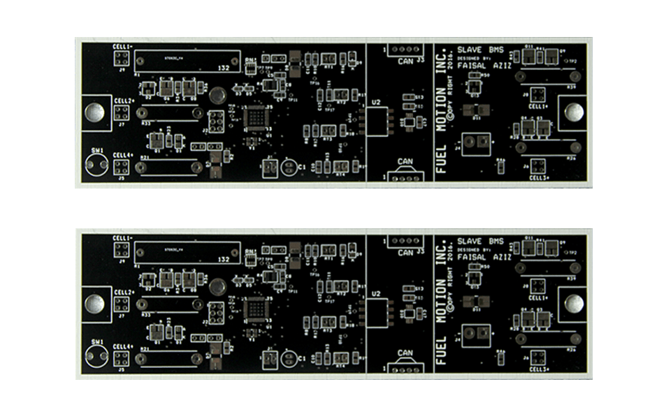
What Is Rogers RT/duroid® 5880?
Bottom line up front: Rogers RT/duroid® 5880 is a PTFE glass-microfiber laminate with a dielectric constant of 2.20 and a dissipation factor as low as 0.0009 at 10 GHz. It is one of the most widely specified materials for microwave and millimeter-wave circuit design, and the material we recommend when signal integrity at high frequency matters more than cost.
RT/duroid® 5880 is produced by Rogers Corporation using a polytetrafluoroethylene (PTFE) dielectric reinforced with randomly oriented glass microfibers. The random microfiber structure keeps the material’s electrical properties isotropic in the X and Y directions, which means consistent, predictable behavior across the panel — a key reason RF engineers trust it for impedance-critical designs.
The laminate is supplied copper-clad in a range of dielectric thicknesses with either electrodeposited (ED) or rolled-annealed copper foil, making it adaptable to both prototyping and volume production.
Key Specifications at a Glance
The two numbers engineers care about most are Dk and Df. Here is how RT/duroid® 5880 performs:
| Property | Typical Value |
|---|---|
| Dielectric constant (Dk) @ 10 GHz | 2.20 |
| Dissipation factor (Df) @ 10 GHz | 0.0009 |
| Base material | PTFE, glass microfiber reinforced |
| Moisture absorption | Extremely low |
| Thermal stability | Electrical performance stable at elevated temperature (up to ~300°C) |
| Copper cladding | ½ oz – 2 oz, ED or rolled foil |
5 Unique Advantages of RT/duroid® 5880
1. Ultra-Low Signal Loss at High Frequencies
With a dissipation factor of just 0.0009, RT/duroid® 5880 loses dramatically less signal than general-purpose laminates. At millimeter-wave frequencies — 24 GHz, 28 GHz, 39 GHz and up to 77 GHz automotive radar bands — this means longer transmission lines, smaller amplifiers, and lower overall system power consumption.
2. Consistent Performance Across a Wide Frequency Band
The dielectric constant stays flat as frequency rises, so impedance calculations made at one frequency remain valid across the band. For filters, couplers, and antenna feed networks that must behave predictably over a wide spectrum, this low dispersion is a decisive advantage.
3. Extremely Low Moisture Absorption
PTFE naturally resists water uptake, and 5880’s moisture absorption is among the lowest of any PCB laminate. Electrical properties stay stable in humid outdoor environments — critical for base station antennas, automotive radar modules, and satellite hardware exposed to changing climates.
4. Excellent Chemical Resistance and Thermal Stability
The material withstands the solvents and etching chemistries used in PCB fabrication without degradation, and its electrical characteristics remain stable through lead-free reflow and other assembly processes, with thermal performance maintained at temperatures up to about 300°C.
5. Isotropic Behavior and Dimensional Stability
Because the glass microfibers are randomly oriented, 5880 etches and machines uniformly in every direction. Fine line-width control, precise laser cutting, and tight impedance tolerances are all easier to hold — which directly improves first-pass yield on RF designs.
Typical Applications
Millimeter-Wave and 5G Antennas
Low loss and low dispersion make 5880 a default choice for 5G millimeter-wave antenna arrays, patch antennas, and feed networks where every fraction of a dB matters.
Automotive Radar (77 GHz)
77 GHz radar front-end boards demand stable dielectric properties across temperature and humidity — exactly where 5880’s low moisture absorption and thermal stability pay off.
Satellite, Aerospace and Defense Electronics
From phased-array radar to satellite communication payloads, designers specify 5880 when performance must be guaranteed in harsh environments.
RF Modules, Filters and Test Fixtures
Power amplifiers, low-noise amplifiers, microstrip filters, couplers, and lab-grade test fixtures all benefit from the material’s predictable, repeatable electrical behavior.
RT/duroid® 5880 vs FR-4 and RO4350B
How does 5880 compare with the two materials buyers most often ask about?
| RT/duroid® 5880 | RO4350B | FR-4 | |
|---|---|---|---|
| Dk @ 10 GHz | 2.20 | 3.48 | ~4.2–4.6 |
| Df @ 10 GHz | 0.0009 | 0.0037 | ~0.02 |
| Suitable frequency range | RF – mmWave (77 GHz+) | RF – mid-band | Digital / low frequency |
| Processing | Requires PTFE-experienced fab | Near-standard FR-4 process | Standard |
| Relative cost | Premium | Mid | Low |
Rule of thumb: choose 5880 for millimeter-wave and lowest-loss designs, RO4350B when you want near-FR-4 processing with solid RF performance, and FR-4 when the design is digital or low-frequency.
Manufacturing Considerations for 5880 PCBs
PTFE laminates are less forgiving than FR-4, so the fabricator you choose matters as much as the material. Key points from our production floor:
- Drilling and hole preparation: PTFE is a soft, thermoplastic material — drilling parameters and desmear preparation must be tuned for reliable plated through-holes.
- Hybrid stackups: bonding a 5880 RF layer to low-cost FR-4 layers saves significant cost on multilayer designs; it requires lamination experience to control warpage and registration.
- Impedance control: low-Dk materials amplify the effect of etch variation on impedance. We hold impedance tolerance to ±10% with coupon-based verification on every RF build.
- Surface finish: ENIG is the most common choice for RF pads and wire-bondable surfaces.
XCE PCB manufactures RT/duroid® 5880 boards from 2 to 72 layers, with panel sizes up to 600×1200 mm, and prototype builds in as fast as 24 hours to IPC-A-600G acceptance criteria.
Why Choose XCE PCB for Rogers 5880 Boards
XCE PCB (Xinchenger Electronics) is a Shenzhen-based high-frequency PCB manufacturer operating since 2009, with a 5,000 m² factory, 80+ engineers, and more than 10,000 completed projects. We stock and process the full range of high-frequency laminates — Rogers RT/duroid®, Taconic, Arlon, and domestic F4B series — under one quality standard.
Because we handle material sourcing, impedance engineering, and fabrication in-house, you get one point of accountability from Gerber review to shipment.
Conclusion
Rogers RT/duroid® 5880 earns its premium price with a combination few materials match: Dk 2.20, Df 0.0009, near-zero moisture uptake, and stable behavior from RF through millimeter-wave frequencies. For 5G antennas, 77 GHz radar, and aerospace RF hardware it remains the benchmark PTFE laminate. The one requirement is a fabricator with PTFE-specific process control — if you have a 5880 design in progress, our engineers can review your stackup and impedance plan before you commit.
Frequently Asked Questions
What is the dielectric constant of Rogers RT/duroid® 5880?
Is RT/duroid® 5880 better than FR-4 for high-frequency PCBs?
Can RT/duroid® 5880 be used in multilayer PCBs?
How fast can you deliver prototype 5880 boards?
Do you support controlled impedance on Rogers 5880 boards?
Need Rogers RT/duroid® 5880 PCBs?
Send us your Gerber files and requirements for a manufacturability review and a tailored quotation.
sales1@xcepcb.com
+86 180 3818 8537