
Lamination, drilling, desmear, CTE stress, and interface-aware routing — the four hard spots of hybrid stackups, and how the factory that builds them daily resolves each.
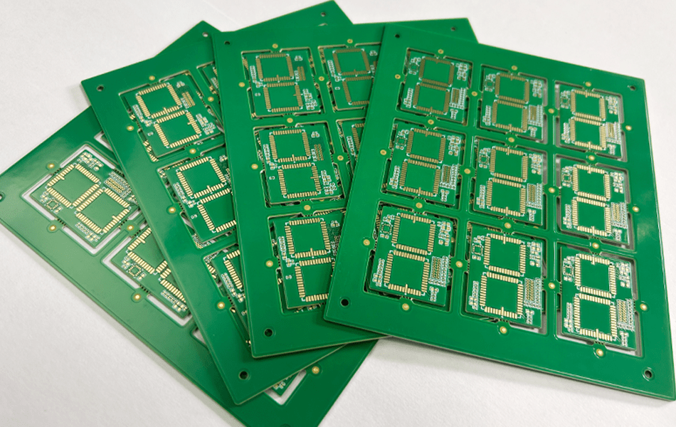
Rogers + FR4 Mixed Stackups: The Short Answer
Bottom line up front: mixing Rogers laminates with FR4 is the standard way to get premium RF performance without paying premium prices for the whole board — but the difficulty is real: two materials with different dielectric behavior, CTE, moisture absorption, and hardness must bond, drill, and plate as one board. The four hard spots are lamination, drilling and desmear, thermal-stress management, and routing across material interfaces.
This article details each difficulty point and how a qualified fabricator resolves them.
Difficulty 1: Material Property Differences
Rogers and FR4 differ significantly in electrical and mechanical behavior:
| Property | Rogers | FR4 — processing implication |
|---|---|---|
| Dielectric constant / loss | Low Dk, low Df — built for RF | Higher loss; keep RF signals off FR4 layers |
| CTE | Lower | Higher; CTE mismatch risks thermal-cycle failures |
| Moisture absorption | Very low | Higher; drives lamination and long-term stability decisions |
| Mechanical hardness | Softer, burr-prone when drilled | Harder, standard drilling parameters work |
The design rule that follows: route high-frequency signal paths on Rogers layers only, reserving FR4 for support or low-frequency circuits — and make sure high-frequency paths never cross material interfaces, which would cause reflection and loss.
Difficulty 2: Lamination
Lamination is the critical step in mixed-material builds:
- Temperature and pressure: Rogers often needs higher lamination temperatures and pressures than FR4 — compatible settings must be found so both bond effectively.
- Lamination cycle: Rogers typically needs longer pre-heating and precise temperature control to prevent warping or overheating, so the cycle is adjusted to preserve both materials’ properties.
- Adhesive selection: the bonding layer must be compatible with both materials — mismatched adhesives cause insufficient interlayer adhesion and delamination.
Difficulty 3: Drilling and Hole Metallization
Drilling: Rogers is softer than FR4 and prone to burrs or delamination. Special drill bits and optimized parameters (speed, pressure) are necessary.
Desmear: Rogers’ chemical stability means standard FR4 desmear chemistry does not bite — specific desmear treatments are essential for clean hole walls and successful copper plating.
Metallization: Rogers’ low moisture absorption reduces wettability during plating, risking poor adhesion. Thorough surface preparation and cleaning before plating are critical.
Difficulty 4: Dimensional Stability and Reliability
Thermal stress: differing CTEs create localized stress at high temperatures — risking warping, delamination, or broken conductive paths. Compensation structures and careful routing to minimize stress concentration are the design countermeasures.
Moisture management: FR4’s higher absorption causes dimensional expansion and degraded dielectric performance where Rogers stays stable. Protective coatings and enclosures minimize environmental impact on the mixed stackup.
Design-Stage Considerations
Three planning decisions prevent most mixed-stackup problems:
- Routing strategy: reserve the Rogers layer for critical signal transmission; keep high-frequency paths away from material interfaces.
- Stack-up optimization: plan layer arrangement against thermal expansion properties and signal integrity together — not sequentially.
- Plating and surface treatment: strictly control plating thickness and quality of hole walls and conductive paths, especially at mixed-material interfaces.
How XCE PCB Builds Hybrid Stackups
Mixed Rogers/FR4 builds succeed on parameter control, material understanding, and careful processing — exactly what a PTFE-experienced line provides. We hold impedance to ±10% with coupon verification, manufacture from 2 to 72 layers up to 600×1200 mm, and ship prototypes in as fast as 24 hours to IPC-A-600G criteria.
Conclusion
The difficulty of mixing Rogers and FR4 concentrates in four places: lamination compatibility, drilling and desmear chemistry, CTE-driven thermal stress, and interface-aware routing. All four are solved problems with the right process controls — and the cost savings versus an all-Rogers build are substantial. If you are planning a hybrid stackup, send it to us; our engineers will review manufacturability and quote with the process plan attached.
Frequently Asked Questions
Why mix Rogers and FR4 in one PCB at all?
What happens if high-frequency traces cross from Rogers to FR4?
Do Rogers and FR4 require different drilling parameters?
Is CTE mismatch between Rogers and FR4 a real reliability risk?
Can you prototype mixed Rogers/FR4 boards quickly?
Planning a Rogers + FR4 Hybrid Stackup?
Send us your Gerber files and requirements for a manufacturability review and a tailored quotation.
sales1@xcepcb.com
+86 180 3341 4657