
Dk 10.2 vs 3.00 · Df 0.0022 vs 0.0010 @ 10 GHz — both are ceramic-filled PTFE with no woven glass, so the choice is purely about one trade: board area against insertion loss.
The Short Answer
RO3010 and RO3003 are the same family of material — ceramic-filled PTFE with no woven glass — separated by one big number: Dk 10.2 versus 3.00. That gap means circuits on RO3010 are about 46% shorter for the same electrical length, so a filter bank or patch array fits in roughly a third of the area. RO3003 gives you about twice the loss margin instead, with Df 0.0010 against 0.0022.
So the decision is not ‘which material is better’ but ‘which constraint binds first’. If your board is area-limited at 2–20 GHz, RO3010 is the answer. If your board is loss-limited — especially at millimeter-wave — RO3003 wins. Everything else in this comparison follows from those two facts.
Two corrections worth making before you design: RO3010 is a ceramic-filled PTFE laminate, not a hydrocarbon thermoset; and RO3003 contains no woven glass, so fiber-weave effects do not apply to it. Both errors are common in online summaries and both change how you plan the build.
Side-by-Side Comparison
| Property (typical) | RO3010 | RO3003 |
|---|---|---|
| Resin system | PTFE + ceramic filler | PTFE + ceramic filler |
| Woven glass | No | No |
| Dk @ 10 GHz | 10.2 ± 0.30 | 3.00 ± 0.04 |
| Df @ 10 GHz | 0.0022 | 0.0010 |
| Thermal conductivity | 0.95 W/(m·K) | 0.50 W/(m·K) |
| Thickness / copper | 0.127–1.524 mm / ½–2 oz | 0.127–1.524 mm / ½–2 oz |
| Fabrication route | PTFE line | PTFE line |
| Sweet spot | Compact circuits, 2–20 GHz | mmWave, loss-critical |
Because both materials run on the same PTFE fabrication route, the processing decision is already made once you pick either of them. The real cost difference comes from the laminate itself — heavily ceramic-loaded RO3010 is the more expensive of the two.
The Size Difference in Numbers
Guided wavelength scales as 1/√Dk. Between these two laminates the factor is √(10.2/3.00) = 1.84, so an element that is electrically a quarter wave at a given frequency becomes 46% shorter:
| Element at 10 GHz | RO3003 | RO3010 |
|---|---|---|
| Quarter-wave length | ≈ 4.3 mm | ≈ 2.3 mm |
| Half-wave resonator | 1.00× | 0.54× |
| Patch radiator area | 1.00× | 0.29× (≈ one third) |
For a multi-pole filter the effect compounds: every resonator shrinks, and because coupling per unit gap also rises with Dk, the gaps between resonators can stay manufacturable while the whole structure contracts. That is exactly the situation where a Dk 3.0 laminate forces you into features below your fabricator’s reliable etch limit.
The Loss Difference in Numbers
At 10 GHz, RO3010’s Df of 0.0022 is about 2.2 times RO3003’s 0.0010. In insertion-loss terms on a short resonator that is a small absolute penalty; on a long feed network or a high-Q filter it accumulates quickly, and it grows with frequency.
In practice: a compact filter on RO3010 at 5–15 GHz will meet spec comfortably, because the resonators are short. A low-noise amplifier input match, a long corporate feed or a 60–80 GHz path is a different story — there the extra loss tangent turns into noise figure, and RO3003’s advantage is worth paying for. The higher thermal conductivity of RO3010 (0.95 vs 0.50 W/(m·K)) partly offsets this in power-handling designs, because heat leaves the board faster.
Processing: Same Route, Different Sensitivities
Neither material is FR-4 friendly. Both need sodium-naphthalene or plasma surface activation, PTFE-specific desmear after drilling, and enhanced electroless copper or PVD seeding before plating. A fabricator who runs a genuine PTFE line can build both; one who does not should be avoided for either.
The sensitivities differ, however. On RO3010, the high Dk makes impedance far more sensitive to thickness and etch variation — the same absolute error in line width translates into a larger percentage impedance shift. On RO3003 the dominant risk is different: thin cores (0.127–0.254 mm are common at mmWave) are flexible and dimensionally mobile, so handling and registration matter more than etch precision. Ask for the tolerance stack on the parameter that actually drives your design.
Extended Applications: Where Each One Earns Its Place
RO3010 extended applications
- Miniature filter banks and diplexers in handheld, airborne or payload-constrained systems, where the enclosure is fixed before the electrical design is frozen
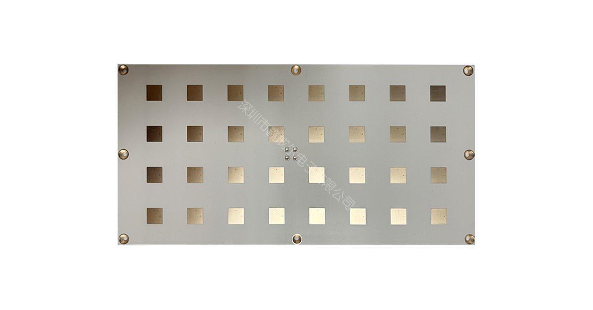
- Compact patch and PIFA antennas for GNSS, telemetry and short-range radar — patch area drops to about one third
- Delay lines and phase shifters in small packages, where physical length has to be squeezed into a module
- Dielectric-loaded waveguide transitions and cavity-style structures that rely on a high Dk to concentrate fields
- Power dividers and couplers where tighter coupling lets you work with wider, more manufacturable gaps
RO3003 extended applications
- 76–81 GHz automotive radar front-ends, where loss and phase stability per channel dominate
- Millimeter-wave backhaul and satcom terminals in Ku/Ka and above, where every tenth of a dB counts
- Low-noise amplifier and front-end modules that cannot afford added loss before the first gain stage
- Phased-array feed networks where amplitude and phase must match across many elements
- Calibration substrates and test fixtures where Dk uniformity across the panel is the requirement
A useful rule of thumb: if you find yourself shrinking gaps below about 0.1 mm to make the circuit fit, you are using the wrong laminate — move up in Dk rather than down in feature size. Our RO3010 advantages overview and RO3003 advantages overview go deeper on each material, and the 3010 vs 3006 comparison covers the middle option at Dk 6.15.
A Practical Selection Checklist
- Board area is fixed and tight? Go RO3010 and accept the extra loss.
- Operating above ~30 GHz? Go RO3003; the loss tangent dominates everything else.
- Gaps falling below 0.1 mm to fit the layout? Move to a higher-Dk laminate instead of pushing the etch process.
- High-power stage with limited heatsinking? RO3010’s 0.95 W/(m·K) helps, but verify against the actual duty cycle.
- Need a middle ground? RO3006 at Dk 6.15 halves the size penalty of RO3003 with Df 0.0020.
How XCE PCB Handles Both
XCE PCB has fabricated ceramic-filled PTFE laminates since 2009 in a 5,000 m² facility: 2 to 72 layers, impedance controlled to ±10%, panel format up to 600 × 1200 mm, 80+ engineers and more than 10,000 delivered projects. RO3010 and RO3003 run on the same in-house PTFE line — plasma desmear, PTFE-specific plating, controlled lamination — alongside a standard FR-4 line for hybrid stack-ups.
Because high-Dk boards are less forgiving of geometry, we control impedance with TDR coupons on the production panel and cross-section the first article of each lot. Samples in as fast as 24 hours when material is in stock.
Conclusion
RO3010 and RO3003 are not rivals so much as two settings of the same dial. Turning Dk up to 10.2 shrinks the circuit to roughly a third of its area and costs you a little over double the loss tangent; turning it down to 3.00 gives you the lowest loss available in the family and asks you to find the space.
Decide which constraint binds — area or loss — and the material follows. Then confirm that whoever builds it runs a real PTFE line, because neither laminate tolerates an FR-4 process no matter how good the design is.
Frequently Asked Questions
What is the dielectric constant of Rogers 3010 versus 3003?
Is RO3010 a hydrocarbon thermoset like RO4003C?
Does RO3003 contain woven glass?
Which is better for millimeter-wave designs, 3010 or 3003?
How much smaller is a filter on RO3010?
Can XCE PCB build both RO3010 and RO3003 with impedance control?
Choosing Between RO3010 and RO3003?
Send us your Gerber files and requirements for a manufacturability review and a tailored quotation.
sales1@xcepcb.com
+86 180 3341 4657