
Communication is RT/duroid 5880’s home market — the datasheet’s own application list leads with antennas and communication systems. What follows is not a feature list but a look at where the numbers actually bite: the loss budget versus FR-4 at Ku-band, the three equipment classes that consume most of the world’s 5880, and the environmental behavior that keeps outdoor radios alive.
The Loss Budget: What Df 0.0009 Buys Over FR-4
The headline numbers: Dk 2.20 ± 0.02 and Df 0.0009 @ 10 GHz, versus FR-4 at roughly 4.4 and 0.020. The consequence scales with frequency and line length:
- Dielectric loss is roughly 20× lower per unit length on 5880 at microwave frequencies — a real gap, not a spec-sheet nicety.
- Low Dk widens the trace. A 50 Ω microstrip on 0.787 mm (31 mil) 5880 is around 2.4 mm wide; on FR-4 the same impedance needs under 1.7 mm. Wider copper means lower conductor loss and looser etch tolerance — directly better manufacturing yield at mmWave.
- TCDk −125 ppm/°C. 5880’s Dk falls as temperature rises — unlike most materials, impedance stays within a tight band across an outdoor enclosure’s thermal swing when the design accounts for the (small) shift.
Where the Volume Goes: Three Equipment Classes
| Equipment | 5880’s role | Why it wins there |
|---|---|---|
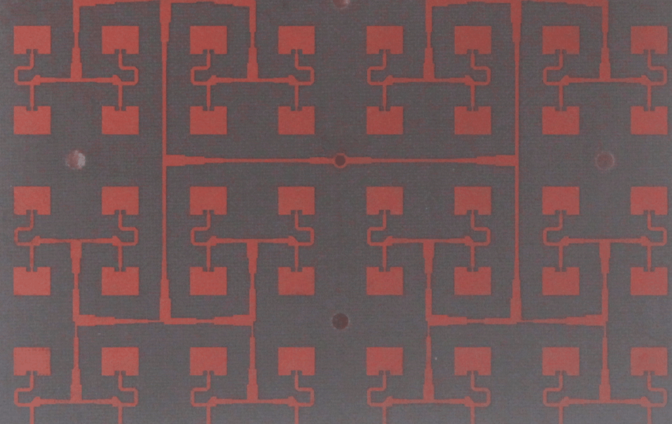
| Base station antennas & arrays | Radiating panels, feed networks | Loss floor, consistent Dk panel-to-panel, proven outdoor aging |
| Millimeter-wave point-to-point backhaul | Front-end and antenna boards, Ku-band and above | Wide repeatable traces, lowest reinforced-PTFE loss |
| Satellite communication payloads & ground radios | RX/TX boards, antenna structures | 0.02% moisture absorption, low outgassing, flight heritage |
The satellite case carries fabrication-specific requirements — controlled-depth routing, hole-wall treatment, handling discipline — covered separately in our satellite machining analysis.
The Environmental Argument: 0.02% and Isotropy
Outdoor communication hardware lives through humidity, temperature and years of duty. Two 5880 properties do quiet work here:
- 0.02% moisture absorption — an order of magnitude below FR-4. A wet monsoon season does not shift impedance or loss on a 5880 antenna; on epoxy-glass laminates, absorbed water visibly raises Df.
- Isotropic, randomly oriented microfiber reinforcement — the Dk is the same in every direction and stable across frequency, so filters and coupled lines behave as simulated even when the layout turns corners.
These properties, plus clean passive-intermodulation behavior on properly specified copper, are why carriers and defense users keep specifying 5880 decades after its introduction.
How XCE PCB Builds 5880 Communication Boards
XCE PCB builds RT/duroid 5880 boards from 2 to 72 layers, impedance controlled to ±10%, panels up to 600 × 1200 mm, with sodium-naphthalene PTH treatment as standard. Samples in as fast as 24 hours when laminate is in stock. Material context: the 5880 laminate overview, the low-loss analysis and the AI radio-layer positioning for comparison.
Frequently Asked Questions
Why is Rogers 5880 preferred for base station antennas?
How much lower is 5880's loss than FR-4 at microwave frequencies?
Is 5880 suitable for mmWave backhaul above 20 GHz?
Does 5880's Dk change with temperature?
Quoting a 5880 Communication Board?
Send us your Gerber files and requirements for a manufacturability review and a tailored quotation.
sales1@xcepcb.com
+86 180 3341 4657