
RO3210 carries the same 10.2 process Dk as RO3010, and almost every electrical number that matters is slightly worse on the 3210: higher dissipation factor, looser Dk tolerance, four times the Z-axis expansion. It exists for a different reason. Its glass reinforcement multiplies the modulus, and that changes what a fabricator can build — thin cores, large panels, heavy copper, high layer counts. This article states the case for RO3210 honestly: what the mechanics buy, and exactly what they cost.
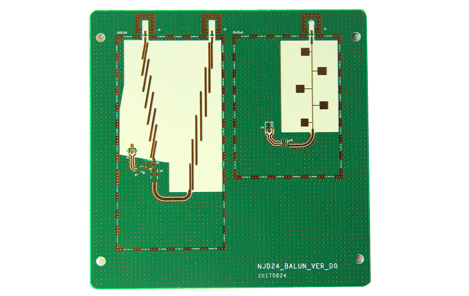
What RO3210 Is
RO3210 belongs to the RO3200 series: ceramic-filled PTFE reinforced with glass fabric. Electrically it is a 10.2-Dk material like RO3010; mechanically it is a different animal, with a tensile modulus around 3,600–4,000 MPa against roughly 1,500 MPa for RO3010 — about two and a half times stiffer.
| Property | RO3210 | Electrical consequence |
|---|---|---|
| Dk (process / design) | 10.2 ± 0.50 / 10.8 | Same process Dk as RO3010 (10.2), but a different design Dk — 10.8 vs 11.20 |
| Df @ 10 GHz | 0.0027 | 23% higher than RO3010’s 0.0022 |
| CTE X / Y / Z | 13 / 13 / 34 | X/Y excellent; Z more than double RO3010’s 16 |
| Thermal conductivity | 0.81 W/m·K | Slightly below RO3010’s 0.95 |
| Td | 500 °C | Family-standard decomposition temperature |
| Copper peel | 11.0 lb/in | Higher than RO3010’s 9.4 — a mechanical gain with a process benefit |
Read the table as a whole and the design intent appears: the 3210 trades a measurable slice of electrical performance for mechanical behaviour. The head-to-head against RO3010 is worked through in the 3010 vs 3210 comparison; this article is about when that trade is the right one.
Advantage 1 — Stiffness Where Thin Cores Are Forced
Deflection under load scales inversely with modulus, and for a plate it scales with the cube of thickness. A 0.254 mm core of RO3010 in a 200 mm panel is flexible enough to sag under its own handling, and flexible enough that assembly fixtures and connectors can distort the RF geometry. The same thickness in RO3210 is 2.5× stiffer: roughly 60% less deflection for the same load.
What that buys is dimensional predictability. A microstrip line’s impedance depends on dielectric height, so a core that bows by 30 µm in the middle of a panel changes impedance across the panel. On thin cores with large panels, the stiff laminate is the difference between a coupon measurement that represents the product and one that represents the middle of a sag.
Advantage 2 — Registration and Panel Stability
Glass fabric constrains in-plane movement. RO3210’s X/Y CTE is 13/13 against RO3010’s 13/11 — similar in magnitude — but the reinforcement also limits the creep and relax behaviour that unfilled PTFE shows under press pressure and during thermal excursions.
For a fabricator this shows up as registration margin. Layer-to-layer budgets run ±0.05–0.075 mm, and the competing error is prepreg cure shrinkage (0.02–0.05%, which is 0.12–0.30 mm across a 600 mm panel). A dimensionally stable core does not remove that error, but it stops the laminate adding its own contribution on top — and on 8- and 10-layer designs the difference is visible in drill registration, not in the specification.
Advantage 3 — Drillability and Edge Quality
Unfilled PTFE is soft, has a thermal conductivity of 0.2–0.5 W/m·K, and smears at the hole wall if the drill rubs instead of cutting. RO3210 adds two things that help the drilling department:
- Glass scaffolding stiffens the stack so the drill exits cleanly and the panel does not deflect under thrust.
- Higher thermal conductivity than pure PTFE (0.81) pulls friction heat away faster, reducing the smear window.
The process rules do not disappear: PTFE still requires plasma or sodium-naphthalene hole treatment, and the aspect ratio still belongs near 6:1. What changes is the yield of clean holes per drill, and therefore the cost of a dense PTH design.
Advantage 4 — Copper Adhesion
Peel strength of 11.0 lb/in against RO3010’s 9.4 is a 17% margin on the interface that decides whether a heavy-copper design survives rework. On power dividers, combiners and antenna arrays with 1 oz or 2 oz copper, the failure mode is not the dielectric but the copper lifting at a reworked pad; the glass-reinforced surface holds better.
The same margin matters on multilayer builds: bonding to a glass-reinforced surface is more forgiving of surface preparation than bonding to unfilled PTFE, which is why thick-copper multilayer designs on 10.2-Dk material often specify RO3210 without any electrical argument at all.
What the Mechanics Cost
| Cost | Size of the cost | When it decides against 3210 |
|---|---|---|
| Df 0.0027 vs 0.0022 | 23% more dielectric loss; at equal electrical length, total dielectric loss tracks Df | Long feed runs, low-noise receivers, tight link budgets |
| Z-CTE 34 vs 16 | 2.1× the barrel strain over temperature; Z-axis strain (34−17)×ΔT = 0.21% across 125 °C vs 0.10% | Very high layer counts, small holes, severe cycling |
| Dk tolerance ±0.50 vs ±0.30 | Wider impedance distribution: ~±1.5% impedance from Dk alone at 10.2 | Phase-matched arrays; narrow-band filters |
| Design Dk 10.8 vs 11.20 | ~4% difference in electrical length if swapped without re-solving | Any design ported from 3010 without re-simulation |
| Both are equally expensive | PTFE-class material and PTFE-class processing | Cost-driven programmes should look at RO4000-class hydrocarbon laminates instead |
The Z-CTE row deserves a note because it is the one usually misread: 34 ppm/°C still beats the 237 of RT/duroid 5880 by a factor of seven, so RO3210 is a reliable multilayer material in absolute terms — it is simply not as good as RO3010 in that one axis.
Claims in Circulation That Do Not Hold
| Claim | Datasheet |
|---|---|
| Df is “around 0.002” | 0.0027 at 10 GHz. Rounding it to 0.002 makes the 3210 look better than RO3010’s 0.0022, which it is not. |
| Thermal weight loss “typically 300 °C” | Td is 500 °C for the whole RO3000/RO3200 family; 300 °C is an FR-4-class number carried over from another data sheet. |
| “Supports laser cutting” | Laser cutting PTFE-class laminates is contraindicated: above roughly 400 °C the polymer decomposes with HF and carbonyl fluoride release and the edge carbonises. Mechanical routing with sharp carbide is the route. |
| “Better dielectric loss than RO3006” | Backwards — RO3006 is 0.0020, lower than 0.0027. The 3210’s advantage over RO3006 is Dk (10.2 vs 6.15, i.e. smaller structures) and stiffness, not loss. |
| “Low CTE keeps electrical performance stable” | CTE is mechanical; phase drift over temperature comes from TCDk (RO3210 −370 ppm/°C). They are different mechanisms with different fixes. |
When to Choose RO3210
Four triggers, in order of how often they decide the question:
- Thin cores in large panels. When dielectric thickness drops below ~0.5 mm and the panel is bigger than a few hundred millimetres, stiffness becomes an impedance-repeatability issue.
- Heavy copper. 2 oz and above: peel margin and drill quality both improve, and the electrical penalty is confined to Df.
- Dense PTH and high layer counts on 10.2-Dk material. The glass helps the drill and the press; check the Z-CTE arithmetic against your cycle anyway.
- Mechanical shock or vibration environment. Conformal-coated thin assemblies in transport or mobile platforms benefit from the modulus.
And three triggers for staying with RO3010: link budget dominated by dielectric loss, phase-matched arrays where ±0.30 Dk tolerance matters, and very high layer counts where Z-CTE 16 is the reliability margin. Both materials are laid out with the same stack-up rules — see the stack-up guide and the RO3010 parameter breakdown.
Conclusion
RO3210 is the glass-reinforced expression of the 10.2-Dk idea: 2.5× the modulus, better peel, easier drilling, more stable panels — at 23% more dielectric loss, twice the Z-axis expansion and a wider Dk window. It is not the upgraded 3010, and its advantages are not electrical. Treat it as a mechanical specification that happens to be electrically excellent, and the material choice becomes straightforward.
XCE PCB processes the full RO3000 and RO3200 families with PTFE-qualified drilling, plasma/Na-naphthalene hole treatment and FEP bonding: 2–72 layers, impedance ±10%, panels to 600 × 1200 mm, 5,000 m² of production space and 80+ engineers, with samples in as fast as 24 hours.
Frequently Asked Questions
Is RO3210 better than RO3010?
What is the dielectric loss of RO3210?
Can RO3210 be laser cut?
Why does glass reinforcement matter for thin cores?
What is the Z-CTE of RO3210 and does it limit layer count?
Does RO3210 need special processing?
Building Thin-Core or Large-Panel RF Boards?
Send us your Gerber files and requirements for a manufacturability review and a tailored quotation.
sales1@xcepcb.com
+86 180 3818 8537