
RO4003C holds a specific position in the laminate market: PTFE-class electrical performance on an FR-4 process line. The five advantages below are the ones that actually move designs and quotations — and one of them is routinely mis-sold, so we correct it with the datasheet rather than repeat it.
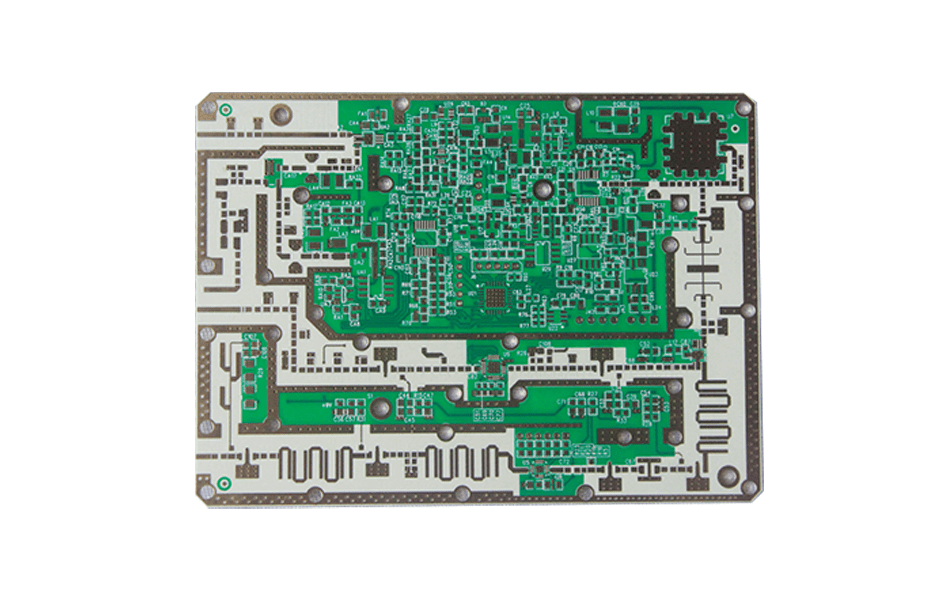
First, What It Is — and Is Not
RO4003C is a woven-glass-reinforced, ceramic-filled hydrocarbon thermoset. It is often introduced as a PTFE substrate — including in older articles on this site — and that is wrong in a way that matters commercially. The material’s whole value proposition is that it is not PTFE: it delivers electrical performance in the PTFE class while running on a standard epoxy/glass PCB line. PTFE laminates demand sodium-naphthalene activation, plasma desmear and special handling; RO4003C demands none of that.
A naming note while we are correcting records: the “RT/duroid” prefix in the title belongs to Rogers’ PTFE product line (RT/duroid 5880, 6002 and similar). RO4003C belongs to the RO4000 series of hydrocarbon laminates alongside RO4350B. The two naming conventions point at different chemistries, and the correct label for this material is RO4003C.
With that established, the advantages that justify specifying it:
Advantage 1: FR-4 Processability, Without FR-4 Loss
This is the commercial engine of the product. RO4003C drills with standard carbide tools, desmears with standard permanganate chemistry, plates through-holes without activation, and laminates on standard cycles. No diamond-coated bits, no plasma etch line, no operator retraining.
The economics compound: traditional PTFE microwave laminates carry not just higher material cost but a process premium — slower drilling, special desmear chemistry, lower yields on the hole-metallization step. RO4003C was engineered so that a fabricator’s existing FR-4 line produces RF-grade boards at FR-4 speed. For high-volume products this is usually the single largest cost lever in the RF BOM.
Advantage 2: The Lowest Loss in the RO4000 Family
Df is 0.0027 at 10 GHz — lower than RO4350B’s 0.0037, and roughly an order of magnitude below standard FR-4 in the 0.020–0.025 range. In absolute terms, on a 50 Ω microstrip the dielectric loss on RO4003C is about 0.10 dB per inch at 10 GHz and about 0.76 dB per inch at 77 GHz.
| Material | Df @ 10 GHz | Process class |
|---|---|---|
| Standard FR-4 | ~0.020–0.025 | Standard epoxy/glass |
| RO4350B | 0.0037 | FR-4 line (brominated, V-0) |
| RO4003C | 0.0027 | FR-4 line (non-brominated) |
| RO3003 (PTFE) | 0.0010 | PTFE line (special handling) |
The table shows the honest position: RO4003C is not the lowest-loss material on the market — PTFE laminates go lower — but it is the lowest-loss option that does not change your process. For 77 GHz automotive radar and high-Q filter work the gap to PTFE matters; for sub-6 GHz infrastructure and most radar, 0.0027 is already inside the link budget with room to spare.
Advantage 3: Lot-to-Lot Consistency
Dk is specified at 3.38 ± 0.05, and Rogers controls it on both 1080 and 1674 glass fabric configurations to the same electrical spec. For a product that ships by the thousands, this is a quieter advantage than loss but it shows up in every production report: filter center frequencies that land where simulation put them, antenna arrays that tune identically across the reel, and no per-lot design adjustments.
Temperature stability backs it up: TCDk is +40 ppm/°C over −50 to +150 °C, the better of the two RO4000 laminates. Across a −40 to +85 °C field swing, Dk moves about 0.5% — for outdoor base station hardware, that bounds frequency drift without needing a temperature-compensating design.
Advantage 4: Assembly Robustness
Three datasheet rows make RO4003C easy to live with through assembly:
Td of 425 °C (5% weight loss) — generous headroom above lead-free reflow, tolerant of multiple assembly cycles and rework. Copper peel of 1.05 N/mm on 1 oz ED foil — the strongest in the RO4000 family, which helps both etch precision and connector-heavy boards. Tg above 280 °C — the resin system does not soften through reflow the way standard FR-4 approaches its limit.
Moisture absorption of 0.06% completes the picture: boards survive humid storage and tropical field conditions without the Dk drift that absorbed water (Dk ≈ 80) causes in cheaper laminates.
The Limits, Stated Honestly
A spec-sheet pitch without the limits is a red flag, so here they are:
- No UL 94 rating. RO4003C is non-brominated and is not V-0. If the end product needs a flammability rating, the family answer is RO4350B — and that is a requirement, not a preference.
- Z-axis CTE of 46 ppm/°C. Fine for thin and mid-count multilayer; on thick stacks with many reflow cycles, RO4350B’s 32 ppm/°C is the more reliable choice.
- Standard cores start at 0.203 mm. Tightly coupled stripline below 8 mil needs RO4350B, whose cores run down to 0.101 mm.
- It is glass-reinforced. Fiber-weave skew is reduced by the fine 1674 fabric, not eliminated.
None of these are disqualifying for the material’s core applications — they are the reasons the family has two members. The full decision table is in our RO4350B vs RO4003C comparison.
How XCE PCB Builds It
XCE PCB builds RO4003C for 2 to 72 layers, impedance controlled to ±10% and verified with TDR coupons on the production panel, panels up to 600 × 1200 mm, hybrid FR-4 stack-ups available and samples in as fast as 24 hours. For the full material and process detail, see the complete RO4003C guide, or the parameter-level breakdown in the 4003C parameters and production guide.
Frequently Asked Questions
Is Rogers RT/duroid 4003C a PTFE material?
What is the dissipation factor of RO4003C?
What are the main advantages of RO4003C over FR-4?
Why choose RO4003C instead of a PTFE laminate like RO3003?
Does RO4003C have any disadvantages?
Can XCE PCB manufacture RO4003C boards with impedance control?
Want RO4003C Quoted on Your Stack-Up?
Send us your Gerber files and requirements for a manufacturability review and a tailored quotation.
sales1@xcepcb.com
+86 180 3341 4657