
RT/duroid 6010.2LM is a ceramic-filled PTFE with a 10.2 process Dk — the same Dk class as RO3010, which is why the two are constantly mistaken for interchangeable. They are not: the 6010.2LM gives up Z-axis thermal expansion and a little loss in exchange for the tightest Dk tolerance in the 10-Dk class and the highest copper peel in the RT/duroid line. This article states the case for the material as the datasheet defines it, and the four figures that decide between it and RO3010.
The Name, First
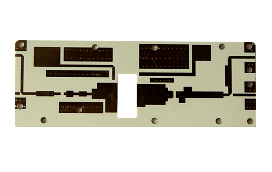
The product is RT/duroid 6010.2LM, from the RT/duroid 6000 line. “6010LM” and “RT6010LM” are shorthands in circulation; the “.2” is part of the designation and the LM stands for low moisture. The substrate is ceramic-filled PTFE — not hydrocarbon, not glass-reinforced fabric — and that construction is what sets both its strengths and its process route.
| Property | RT/duroid 6010.2LM | What it means in design |
|---|---|---|
| Dk, process / design | 10.20 ± 0.25 / 10.7 | Tightest tolerance in the 10-Dk class; use 10.7 for wideband solving |
| Df @ 10 GHz | 0.0023 | Low for a 10-Dk material, slightly above RO3010’s 0.0022 |
| TCDk | −425 ppm/°C (−50…170 °C) | The figure that governs phase drift — large, and negative |
| CTE X / Y / Z | 24 / 24 / 47 | Z is three times RO3010’s 16: barrel strain is the trade-off |
| Thermal conductivity | 0.86 W/m·K @ 80 °C | Good for a PTFE composite; heat still leaves through vias |
| Density | 3.1 g/cm³ | Heavy — ceramic loading is high; mass-sensitive designs should weigh it |
| Moisture absorption | 0.01% | A fifth of RO3010’s 0.05%: the “LM” in the name |
| Copper peel | 12.3 pli (2.1 N/mm) | Highest in the RT/duroid family; rework and heavy-copper margin |
| Td | 500 °C | PTFE-class thermal decomposition, lead-free compatible |
| Flammability | UL 94 V-0 | V-0 without relying on brominated additives |
Advantage 1 — ±0.25 Tolerance at 10.2
At Dk 10, physical tolerances are unforgiving. A 50 Ω microstrip on 0.635 mm material is only about 0.49 mm wide, so a 0.25 Dk spread and a 0.05 mm etch error move impedance by percentages that a wider 3.0-Dk line would absorb without noticing.
A ±0.25 Dk window (versus ±0.30 for RO3010) buys roughly ±1.2% impedance on Dk alone — small in isolation, decisive in a narrow-band filter or in a phase-matched array where every line must agree with its neighbours. It also buys predictability across material lots: a tighter window means the second run etches closer to the first without re-solving.
Advantage 2 — Peel Strength and Heavy Copper
12.3 pli (2.1 N/mm) after solder float is the highest copper adhesion in the RT/duroid line — 17% above RO3010-class values and well above the 7.9 pli of 6035HTC. For designs with 1–2 oz copper on combiners, couplers and antenna arrays, that margin is what survives rework: the failure mode on a reworked heavy-copper pad is copper lifting from the dielectric, not the joint itself.
The related mechanical numbers support the picture: tensile modulus ~931 MPa along X and ~559 MPa along Y, flexural modulus 4.4/3.8 GPa, compressive modulus 2.1 GPa, and deformation under load of 2.1% at 50 °C/7 MPa — stiff for a PTFE composite, and stable enough that connector press-fit forces do not creep the board over life.
Advantage 3 — Low Moisture by Design
0.01% water absorption is five times better than RO3010 and fifty times better than FR-4. In sealed enclosures it hardly matters; in radomes, antenna housings and outdoor units it is the difference between a first-year alignment and a maintenance visit.
Moisture matters electrically through Dk: absorbed water raises effective permittivity and therefore lengthens electrical paths and detunes resonators. A PTFE composite at 0.01% barely moves; the practical benefit shows up as phase repeatability after humidity cycling rather than as an insertion-loss number.
Advantage 4 — Thermal Conductivity Above Its Class
0.86 W/m·K is not a headline number next to 6035HTC’s 1.44, but for a 10-Dk material it is useful: a 0.635 mm layer has a thermal resistance of t/k = 0.74 K·cm²/W, which at 5 W/cm² of dissipated power means about 3.7 K across the dielectric — small in absolute terms, but enough that a compact high-Dk power structure does not become a hot spot purely because of the substrate.
What It Costs, Stated Plainly
| Cost | Number | When it decides against 6010.2LM |
|---|---|---|
| Z-axis CTE | 47 ppm/°C — nearly 3× RO3010’s 16 | Dense PTH, many layers, severe cycling: barrel strain (47−17)×ΔT is 0.38% across 125 °C |
| Phase drift | TCDk −425 ppm/°C | Across 200 °C, Dk falls 8.5%, electrical length shortens ~4.3% — about 170° of phase on a 100 mm line at 10 GHz |
| Loss | Df 0.0023 vs 0.0022 | Rarely decisive; at equal electrical length the difference is ~4% of dielectric loss |
| Weight | 3.1 g/cm³ | Airborne and space payloads where mass is a line item |
| Process | PTFE route: plasma/Na-naphthalene, FEP bonding, dry machining | Programmes expecting an FR-4 process line |
The phase number deserves attention because it is the largest of the costs and the least often modelled. A material with −425 ppm/°C is not thermally unstable in the mechanical sense; it is thermally drifting in the electrical sense, and beam-forming networks must calibrate for it or choose another material. RO3010, with a lower magnitude TCDk, is the usual answer when phase matters more than tolerance.
Claims in Circulation That Do Not Hold
| Claim | Datasheet |
|---|---|
| Df “less than 0.0019” | 0.0023 at 10 GHz. The lower figure would make it better than RO3010; it is not — the two are within 4% of each other, with RO3010 lower. |
| Thermal weight loss “300 °C” | Td is 500 °C. 300 °C is FR-4 language; using it understates the material and misleads reflow assumptions. |
| “Supports laser cutting” | No: PTFE composites decompose above ~400 °C with HF and carbonyl fluoride release, and the edge will not bond. Mechanical routing only. |
| “Lower loss than RT/duroid 3006” | Backwards: 3006 is 0.0027 nominally, and 6010.2LM is 0.0023 — the LM material is lower, but the 3006 comparison that circulates quotes the wrong Dk direction as well (3.5 vs 6.15). |
| “Low CTE keeps electrical performance stable” | Mixes two mechanisms: CTE is mechanical expansion, phase drift comes from TCDk. On this material TCDk is large (−425), so the claim inverts the risk. |
When to Choose It — and When to Choose RO3010
Four situations favour 6010.2LM:
- Narrow-band filters and diplexers where the Dk window, not the loss, sets yield.
- Heavy-copper compact structures — combiner and coupler boards where peel margin decides rework cost.
- Humid or condensing environments where 0.01% absorption protects alignment.
- Legacy programmes already qualified on the 6010 family, where re-qualification costs more than the material difference.
Three situations favour RO3010 instead: multilayer builds where Z-CTE 16 versus 47 is the reliability margin; phase-critical arrays where a large negative TCDk is unwelcome; and weight-sensitive designs where 3.1 g/cm³ is a penalty. The full family context sits in the RO3000 series guide, and the stack-up rules are common to both — see the stack-up article.
Conclusion
RT/duroid 6010.2LM is not the better 10-Dk material; it is the tighter one. Its case rests on a ±0.25 Dk window, 2.1 N/mm peel and 0.01% moisture, paid for with three times the Z-axis expansion of RO3010 and the largest negative TCDk in the family. Specify it where tolerance, adhesion and humidity define the yield, and expect to calibrate phase — that is the honest contract with this laminate.
XCE PCB processes RT/duroid 6010.2LM and the RO3000 family with PTFE-qualified drilling, plasma/Na-naphthalene hole treatment and FEP bonding: 2–72 layers, impedance ±10%, panels to 600 × 1200 mm, 5,000 m² of production space and 80+ engineers, with samples in as fast as 24 hours.
Frequently Asked Questions
Is RT6010LM the same as RO3010?
What is the dielectric constant of 6010.2LM?
Why does the low moisture content matter?
What is its thermal coefficient of dielectric constant?
Can 6010.2LM be laser cut?
How does it compare with RO3210 at the same Dk?
Sourcing High-Dk PTFE Boards?
Send us your Gerber files and requirements for a manufacturability review and a tailored quotation.
sales1@xcepcb.com
+86 180 3818 8537