
The Rogers RO3000 series is a family of ceramic-filled PTFE laminates — no glass fabric — offered at four dielectric constants from 3.0 to 10.2, with a glass-fibre-reinforced sibling family (RO3200) where stiffness matters more than the last tenth of a dB. Model lists circulating on the web make the family look bigger than it is: they include a bonding film and at least two products Rogers does not make. This article sets out the family as it actually exists, with datasheet numbers, and then what each member is for.
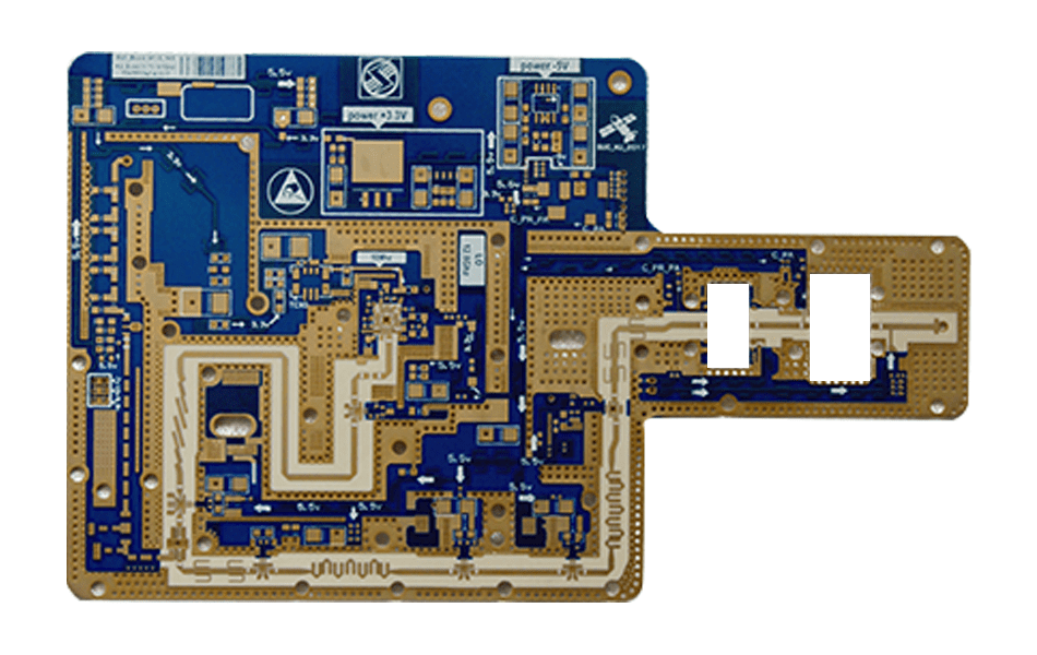
What the Family Is — and Is Not
RO3000 laminates are ceramic-filled PTFE. The filler system gives them a stable, frequency-flat Dk and moisture immunity (absorption 0.02–0.06%), and the PTFE base gives them the lowest dissipation factors in their Dk classes. The family is glass-free: construction is filled PTFE, not woven glass — which removes glass-weave Dk variation and makes the material electrically isotropic. Descriptions that add “glass fibre reinforcement” to RO3000 are describing the wrong family.
Two practical consequences follow from the construction. First, processing: PTFE does not respond to standard FR-4 desmear chemistry and needs plasma or sodium-naphthalene hole treatment, with bonding done by FEP-family adhesive films at 260–300 °C. Second, mechanics: filled PTFE is softer and lower-stiffness than glass-reinforced laminates, which is exactly what the RO3200 series was created to fix.
The Verified Model List
| Model | Dk (process) | Df @ 10 GHz | CTE X/Y/Z, ppm/°C | Thermal cond., W/m·K |
|---|---|---|---|---|
| RO3003 | 3.00 ± 0.04 | 0.0010 | 17 / 16 / 25 | 0.50 |
| RO3035 | 3.50 ± 0.05 | 0.0015 | 17 / 17 / 24 | 0.50 |
| RO3006 | 6.15 ± 0.15 | 0.0020 | 17 / 17 / 24 | 0.79 |
| RO3010 | 10.2 ± 0.30 | 0.0022 | 13 / 11 / 16 | 0.95 |
RO3010 deserves its own line of praise: its three-axis CTE of 13/11/16 is at or below copper’s 17 on every axis — the best thermal-expansion match to copper in the PTFE world, and the reason its multilayer reliability exceeds the rest of the family. The individual members are covered in depth in the RO3010 parameter guide and the RO3003 advantages article.
The glass-fibre-reinforced siblings, RO3200 series, share the same Dk values with different mechanics:
| Model | Dk | Df @ 10 GHz | Added by the glass |
|---|---|---|---|
| RO3203 | 3.00 | 0.0016 | Stiffness and drillability; slightly higher loss than RO3003 |
| RO3206 | 6.15 | 0.0027 | Same trade — mechanical robustness for Df |
| RO3210 | 10.2 ± 0.50 | 0.0027 | ~2.5× the modulus of RO3010; Z-CTE 34 and looser Dk tolerance |
The comparison that ends most 3010-vs-3210 debates: electrically RO3010 wins across the board (Df 0.0022 vs 0.0027, Z-CTE 16 vs 34, tighter Dk tolerance), so RO3210 is chosen for mechanical reasons — thin cores, large panels, demanding drilling — not electrical ones. The head-to-head is worked through in the 3010 vs 3210 comparison.
Three Entries in the Circulating Model List That Fail Verification
Model lists for this series repeat three entries that do not hold up against the Rogers portfolio:
| Listed as | Listed parameters | What it actually is |
|---|---|---|
| Rogers 3001 | Dk 2.94, Df 0.0021 | A real product number — but a PTFE bonding film, not a circuit laminate. The parameters quoted are the film’s; it belongs in the stack-up, not in a model comparison of boards. |
| Rogers 3002 | Dk 3.0, Df 0.0017 | No RO3002 exists in the Rogers PTFE portfolio. The parameters describe a plausible 3.0-class laminate — which the family already has: RO3003. |
| Rogers 3015 | Dk 15.2, Df 0.0030 | No 15.2-Dk RO3000 product exists; the family tops out at RO3010 (10.2), and Rogers’ PTFE line does not reach 15.2. Treat any 3015 datasheet as fabricated. |
The pattern is recognisable: invented model numbers wrapped around plausible parameters. They cost a buyer nothing until a quotation is requested for a part number nobody can source — or until a drawing specifies one, at which point the “equivalent” offered is whatever the factory prefers.
Choosing Within the Family: Loss versus Size
The four Dk grades answer one question: how much board area is the design willing to trade for loss?
- 3.0 (RO3003) — the low-loss workhorse: 0.045 dB/in at 10 GHz, wide 50 Ω traces, the default for front ends, filters and satellite payload work.
- 3.5 (RO3035) — a small step up in Dk with loss still under 0.002; common in automotive-radar-class designs and impedance-specific structures.
- 6.15 (RO3006) — guided wavelength shrinks ~28% versus 3.0; patch antennas and couplers get materially smaller.
- 10.2 (RO3010) — components and antennas shrink to roughly half the linear size of 3.0-class designs; the loss penalty is real (0.19 dB/in) but — the counter-intuitive part — total dielectric loss at equal electrical length depends on Df, not Dk, because the shorter line cancels most of the higher attenuation. High Dk is a size decision, not a loss decision.
One further caution: the published design Dk of RO3010 is 11.20, not the 10.2 process value. Solving a wideband design with the process Dk mis-scales every electrical length — the mechanism is explained in the 3010 vs 3006 selection guide.
Manufacturing Notes That Come with the Family
- Hole preparation: plasma or sodium-naphthalene treatment only; permanganate desmear has no effect on PTFE and leaves smear that plating will not cover.
- Bonding: RO3001 or FEP films at 260–300 °C — and if the drawing says “3001”, that is the bonding step, not a layer of laminate.
- Machining: dry drilling and routing; sharp carbide, low feed; finished dimensions verified after routing because the material creeps under press pressure.
- Aspect ratio: ~6:1 for PTFE builds, with high-elongation copper plating specified for reliability on the higher-Z-CTE members (RO3003 Z 25 is benign; RO3006 24 likewise; the RO3200 glass layers help here too).
The process contrasts with RO4000-series hydrocarbon laminates, which fabricate on standard FR-4 lines — a comparison set out in the RO4000 selection guide.
Where the Family Goes
| Application | Typical member | Why this grade |
|---|---|---|
| Satellite and payload RF | RO3003 | Lowest family Df, moisture immunity, outgassing-friendly PTFE construction |
| Automotive radar sensors | RO3035 / RO3003 | Flat Dk across temperature for phase stability at 77 GHz |
| Patch antennas, GNSS | RO3006 / RO3010 | High Dk shrinks the radiator; tight Dk tolerance keeps the resonance on frequency |
| Filters, couplers, DC blocks | RO3006 / RO3010 | Compact structures with predictable phase |
| Power amplifiers, heatsinking designs | RO3010 | Best thermal conductivity in the family (0.95) plus CTE below copper on all axes |
Conclusion
The RO3000 series is four laminates and one bonding film: RO3003, RO3035, RO3006 and RO3010, with RO3200-series glass-reinforced siblings where stiffness is the priority and RO3003G2 where a thermoset variant is preferred. Everything else in the circulating model lists — 3002, 3015, “3001 the laminate” — fails verification. Specify from the verified table, and the family covers the full span from the lowest-loss 3.0 designs to compact 10.2 antennas with a consistent, well-documented process route.
XCE PCB fabricates the full RO3000 and RO3200 families with PTFE-qualified processing: 2–72 layers, impedance ±10%, panels to 600 × 1200 mm, 5,000 m² of production space and 80+ engineers, with samples in as fast as 24 hours.
Frequently Asked Questions
Does the Rogers RO3000 series contain glass fibre?
Is Rogers 3001 a laminate?
Do Rogers 3002 and 3015 exist?
What is the difference between RO3010 and RO3210?
Which RO3000 model should I choose for a compact antenna?
Why is RO3010 considered reliable for multilayer boards?
Sourcing RO3000-Series Boards?
Send us your Gerber files and requirements for a manufacturability review and a tailored quotation.
sales1@xcepcb.com
+86 180 3818 8537