
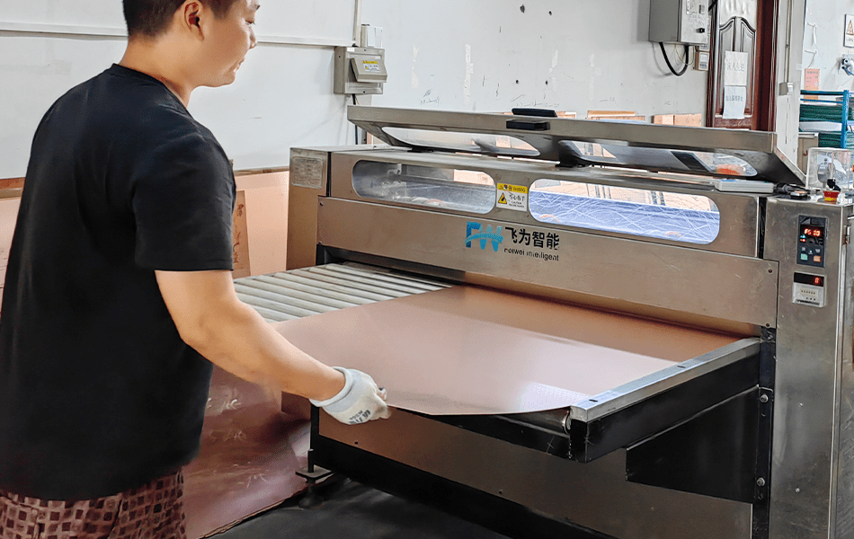
Cutting is the first operation on a high-frequency panel and the one most often treated as warehouse work. It is not. Every later step — pinning, lamination, drilling, routing — inherits the datum that this saw cut created, and on a laminate that costs ten to twenty times FR-4 per square metre, a mis-cut sheet is not scrap material, it is scrap money. These are the requirements that matter and the three cutting methods that look precise and destroy PTFE.
Why the First Cut Matters More Than It Looks
A 600 × 1200 mm sheet of RO4350B costs an order of magnitude more than the same area of FR-4, and a sheet of PTFE-class laminate more again. That economic fact changes what “cutting accuracy” means. On FR-4 a mis-cut panel is a yield event; on high-frequency laminate it is a purchase-order event, and on a hybrid it can strand a whole build because the RF core and the FR-4 core have to be cut to the same datum to laminate flat.
The technical half matters as much. Every subsequent operation references the tooling holes drilled into the blank, so the quality of the cut edge — square, burr-free, undistorted — propagates through pinning, lamination, drilling and routing. A burr that lifts the bondply by 25 µm at the panel edge becomes a void that opens under thermal cycling. A blank cut 0.3 mm out of square becomes a registration error that shows up as annular-ring breakout four steps later.
This is step one of the twelve-step manufacturing sequence. The steps that follow assume the panel is flat, square and correctly sized — all three of which are decided here.
Requirement 1 — Know What the Tolerance Is For
Blank cutting does not need ±0.1 mm. The final board outline is routed later, to ±0.1–0.15 mm, with the routing programme referenced to the same tooling holes. What the blank cut has to deliver is a panel that fits the press, sits square on the pinning table, and leaves enough margin around every array that the router has somewhere to cut.
| Feature | Practical tolerance | What it protects |
|---|---|---|
| Blank dimension | ±0.2 mm (saw) to ±0.1 mm (CNC) | Press fit and panel registration |
| Squareness | ≤0.1 mm per 300 mm | Layer-to-layer registration across the panel |
| Tooling hole position | ±0.025 mm, drilled | The datum every later step uses |
| Edge burr height | ≤0.05 mm | Void-free bond line at the panel edge |
| Tooling border | 15–25 mm all round | Pinning, routing clearance, test coupon area |
Then the constraint that makes a tight tolerance harder to hold than it sounds: the laminate moves with temperature, and on a 600 mm span the movement is larger than the tolerance. At 26 ppm/°C in X, a 600 mm PTFE panel grows 0.31 mm over a 20 °C swing in shop temperature. The same panel in RO4350B, at 10 ppm/°C, moves 0.12 mm.
| Laminate | CTE X / Y (ppm/°C) | 600 mm growth over 20 °C |
|---|---|---|
| Taconic TLY-5 | 26 / 15 | 0.31 mm |
| RT/duroid 5880 | 31 / 48 | 0.37 mm |
| RO4350B | 10 / 12 | 0.12 mm |
| RO4003C | 11 / 14 | 0.13 mm |
| FR-4 | ≈16 / 16 | 0.19 mm |
The conclusion is procedural, not metrological: measure and cut at a stated temperature (20 ± 2 °C is the usual shop standard), and treat any measurement taken on a cold morning as a different panel. This is also why the tolerance is quoted against the tooling holes rather than the sheet edge — the holes travel with the panel, the edge does not.
Requirement 2 — Edge Quality: What a Burr Actually Costs
The common statement is that a rough cut edge causes signal reflection or loss. That is not what happens. The blank edge sits outside the circuit, in the tooling border, and is routed away before the board is finished — it never carries an RF current. The real costs are mechanical and they are all worse than a reflection:
- Lamination voids. A burr or a rolled edge holds the bondply off the copper by 20 to 50 µm. The gap survives the press and becomes a void along the panel edge, which is exactly where the routing cut will later release the stress. Delamination starts there.
- Registration drift. A blank that is not square cannot be pinned square. On an eight-layer build the error compounds once per layer, and it appears as breakout at the inner-layer annular ring rather than as an obviously crooked panel.
- Resin starvation and copper smear. A torn PTFE edge has a ragged, high-surface-area profile that draws resin away from the edge of the array during pressing, and a burred copper edge can fold over and short a fine-pitch pattern after routing.
- Contamination. Loose fibre and filler dust from a bad cut migrates onto the copper before lamination. It does not come off in the press.
The measurable target is a burr height at or below 0.05 mm with no rolled edge, no delamination visible at the cut, and no fibre pull-out on woven-glass PTFE. If the cut edge has to be examined at ×10 to decide, it is not in specification.
Requirement 3 — Match the Method to the Material, and Do Not Laser PTFE
Three methods get proposed for every laminate, and two of them are wrong for PTFE. The table is the short version; the reasons follow.
| Method | PTFE (5880, TLY-5) | Ceramic-filled PTFE (RO3006/3010) | RO4000 thermoset | FR-4 |
|---|---|---|---|---|
| Carbide saw | Yes — sharp, high rake, low feed | Yes — diamond-coated blade | Yes — standard | Yes |
| CNC routing | Yes for complex outlines | Yes | Yes | Yes |
| Shear / guillotine | <1 mm only — cold flow, rolled edge | No — edge chipping | Thin only | Yes |
| Laser | No — HF fumes, carbonised edge | No — glass and filler melt, char | No — charred resin | Depths, not blanks |
| Waterjet | No — water and grit in a soft edge | No | No | No |
Laser. PTFE decomposes above roughly 400 °C into hydrogen fluoride and carbonyl fluoride — a serious industrial-hygiene problem — and leaves a carbonised edge that is both a cosmetic reject and a leakage risk. The cut looks wonderfully straight. It is also unusable: the charred layer does not bond, and the edge has to be milled back anyway, at which point the laser achieved nothing except fume extraction.
Waterjet. It solves the heat problem and creates a worse one. An abrasive waterjet leaves water and garnet grit embedded in the open, fibrous structure of a PTFE edge. PTFE absorbs very little water (0.02% by the datasheet), but the FR-4 core of a hybrid does not, and the grit is a permanent inclusion at the bond line. Both are delamination sources under press and reflow.
Shear. Fine on thin FR-4, wrong on PTFE, because PTFE cold-flows: a sheared edge is not cut so much as displaced, and it keeps creeping after the panel is stacked. If a shear is the only tool available, restrict it to materials under 1 mm and check the edge with a straight edge and light.
What actually works is unglamorous: a sharp carbide blade, correct rake angle, feed rate slow enough that the PTFE is cut rather than smeared, and a blade change schedule based on metres cut rather than on visible wear. Worn carbide smears PTFE — the symptom is a shiny, rounded edge that looks smooth and does not bond.
Requirement 4 — Cut, Relax, Then Cut Again
Laminate arrives with residual stress from its own press cycle, and cutting releases it. On a large panel the release shows up as bow or a change in dimension minutes after the cut — the panel is straight when it leaves the saw and 0.3 mm out by the time it reaches the pinning table.
The production answer is a two-stage cut. Rough-cut the blank 3 to 5 mm oversize, let it relax flat (a few hours is enough at shop temperature; overnight if the sheet was stored cold), then finish-cut to the tooling dimension. It costs one extra pass and it removes the single most confusing source of dimensional error in the whole flow, because the second cut is measuring a relaxed sheet rather than a stressed one.
Two supporting habits. Nest the array symmetric about the panel centre so that the remaining material is balanced — an array crowded to one corner bows that corner. And on PTFE, remember that the material also cold-flows under clamp pressure: the blank that measured correctly before lamination may be different after it, which is why the final outline is routed, not cut, and why the routing programme is referenced to drilled holes rather than to the sheet edge.
Requirement 5 — Manage Heat, Dust and Tool Wear Together
These three are one problem: cutting generates heat, heat softens or decomposes the polymer, and a dull tool generates more heat.
- Heat. Keep the cut cool with air and extraction, not with liquid. Water-based coolant on a laminate that is about to be laminated is a moisture source at the interface; on a hybrid it is a moisture source in the FR-4 core specifically, which is the layer that absorbs it. If the material has been stored cool, let it come to room temperature sealed, so condensation forms on the bag and not on the sheet.
- Dust. Ceramic-filled laminates (RO3006, RO3010, Taconic RF-10) cut into a respirable abrasive dust. Extraction at the cut line, not at the room, and respiratory protection where the extraction cannot keep up. PTFE dust that reaches decomposition temperature in a worn cut is a polymer-fume hazard; the same rule — extract at source — covers both.
- Tool wear. Ceramic filler is abrasive enough that a blade which still cuts FR-4 will chip RO3010. Diamond-coated carbide for filled materials, and a wear check that looks at edge quality on the actual product rather than at the blade.
Consideration 1 — Tooling, Registration and the Kerf
Three numbers decide whether the cut panel can be used. The tooling border of 15 to 25 mm carries the pin holes, the routing clearance and usually the impedance coupon; below 15 mm the router starts cutting into the pinning area. The kerf of 1.5 to 3 mm has to be included in every panelisation calculation — a 2 mm kerf across a 600 mm panel is small in material but decisive in layout.
And the tooling holes are drilled, never punched, on PTFE. Punching cold-flows the polymer and leaves a tapered, cracked hole that will not hold a pin straight; a drilled hole at ±0.025 mm becomes the datum that every layer of the stack is pinned to. On a hybrid, the RF core and the FR-4 core are drilled from the same programme, in the same fixture, or they will not register.
The protective film stays on through cutting. It prevents the scratch and the handling mark that later reads as a surface defect under the mask, and it keeps dust off the copper. It comes off before lamination, with the residue removed — a film left on a PTFE sheet through the press is a guaranteed delamination.
Consideration 2 — Record Every Sheet, Because the Stack Depends On It
This is the part of cutting that pays for itself later. Sheet thickness varies lot to lot, and Dk varies with it — the extreme case being 0.101 mm RO4350B, where the datasheet footnotes a Dk of 3.36 against the 3.48 nominal. If the cutting station records, per sheet, the measured thickness, the lot number and the weave direction, the stack engineer can choose the bondply that lands the pressed height where the impedance model wants it, instead of discovering the deviation after TDR.
Weave direction matters for the same reason on woven-glass PTFE: dimensional stability and Dk both differ along and across the weave. Keeping the RF direction aligned to the same weave axis on every sheet removes a variable that no amount of etching control can fix afterwards. The stack side of this is in the stack-up design guide, and the data-package side — how the pressed height and the Dk basis get written down — in the hybrid design file guide.
Consideration 3 — Inspect, Deburr, and Do Not Polish
Post-cut inspection is dimensional plus visual, and it needs the right light: a low-angle lamp makes a 0.05 mm burr obvious and a straight-on lamp hides it. Measure dimensions at the tooling holes, not the corners. Check for edge delamination with a ×10 loupe on every lot of PTFE, and for fibre pull-out on woven-glass grades.
Deburr by hand with a controlled blade or a fine abrasive block, in one direction, away from the copper. Do not polish the edge. Polishing pulls fibres out of a woven PTFE and burnishes the polymer into a smeared layer that looks excellent and bonds poorly — the same failure as a worn blade, achieved deliberately. Solvent wiping on a PTFE edge is also pointless-to-harmful: it removes nothing that matters and can leave a residue that outgasses in the press.
Where Cutting Goes Wrong
| Symptom found later | Real cause at the saw | Prevention |
|---|---|---|
| Voids along the panel edge after lamination | Burr or rolled edge holding the bondply off the copper | Burr ≤0.05 mm, edge inspected under low-angle light |
| Annular-ring breakout on inner layers | Blank out of square, or tooling holes punched instead of drilled | Squareness ≤0.1 mm/300 mm; drilled pins at ±0.025 mm |
| Edge delamination after thermal cycling | Carbonised or water-contaminated edge from laser or waterjet | Carbide saw for PTFE; no liquid coolant |
| Panel dimension drifts between shifts | Thermal expansion — 0.31 mm per 20 °C on a 600 mm PTFE panel | Cut and measure at 20 ± 2 °C; record temperature |
| Impedance off target despite correct widths | Sheet thickness / Dk lot not recorded, bondply chosen by nominal | Measure thickness and record lot per sheet |
| Torn edge that will not bond | Worn blade smearing PTFE instead of cutting | Blade change by metres cut, not by appearance |
Cutting Checklist
| # | Check | Pass condition |
|---|---|---|
| 1 | Method matches material | Carbide saw or router; no laser, no waterjet on PTFE |
| 2 | Blade condition | Diamond-coated for filled grades; changed by metres cut |
| 3 | Material conditioned | At shop temperature, sealed until opened, dry |
| 4 | Stress relief | Rough-cut oversize, relax, then finish cut |
| 5 | Blank dimension and squareness | ±0.2 mm and ≤0.1 mm per 300 mm |
| 6 | Edge quality | Burr ≤0.05 mm, no rolled edge, no fibre pull-out |
| 7 | Tooling holes | Drilled at ±0.025 mm, same programme for RF and FR-4 cores |
| 8 | Tooling border | 15–25 mm, clear of pinning and coupon area |
| 9 | Kerf included in panelisation | 1.5–3 mm accounted for in the array layout |
| 10 | Sheet records | Thickness, lot, weave direction logged per sheet |
Conclusion
Cutting is cheap to do well and expensive to do casually. The five requirements come down to: cut with a sharp carbide tool, cut oversize and finish after the stress has gone, keep liquid away from a laminate that is about to be pressed, hold the datum at drilled holes rather than at the sheet edge, and write down each sheet’s thickness and lot while it is still in your hand. The three methods to refuse on PTFE — laser, waterjet and shear on thick stock — all produce an edge that looks acceptable and bonds badly.
XCE PCB cuts and pins hybrid panels up to 600 × 1200 mm in-house, on Rogers, Taconic and F4B laminate, building 2–72 layers with impedance ±10%, 5,000 m² of production space and 80+ engineers, samples in as fast as 24 hours. The interface chemistry that follows the cut is covered in the hybrid lamination analysis and, for PTFE, in the 5880 and FR-4 lamination guide.
Frequently Asked Questions
What tolerance is needed when cutting high-frequency substrate?
Can you laser cut PTFE laminate?
Is waterjet cutting suitable for high-frequency laminate?
Why cut a panel oversize and then cut it again?
How much does temperature affect panel dimensions?
Does edge roughness on the cut affect insertion loss?
Need a Hybrid Panel Cut and Pinned to Tolerance?
Send us your Gerber files and requirements for a manufacturability review and a tailored quotation.
sales1@xcepcb.com
+86 180 3341 4657