
Three datasheet corrections frame this analysis: the earlier version cited X/Y CTE of 12 ppm/°C (the official figures are 31/48, with Z at 237), thermal conductivity of 0.64 W/m·K (0.20 is the datasheet value), and an unsourced thermal case study — all removed. What remains is the defensible version of why 5880 earns its place in 5G and mmWave hardware: loss physics, phase consistency and humidity immunity.
The Corrected Datasheet Baseline
| Property | Value | mmWave significance |
|---|---|---|
| Dk @ 10 GHz | 2.20 ± 0.02 | Tight band = phase-matched arrays are practical |
| Df @ 10 GHz | 0.0009 | ~20× lower dielectric loss than FR-4 |
| CTE X / Y / Z | 31 / 48 / 237 ppm/°C | Z 237 — multilayer designs need plating rules or 5880LZ |
| Thermal conductivity | 0.20 W/m·K | Low — power amplifiers need separate thermal design |
| Moisture absorption | 0.02% | Outdoor AAUs and radomes keep their loss numbers in rain |
Where 5880 Fits in 5G Hardware
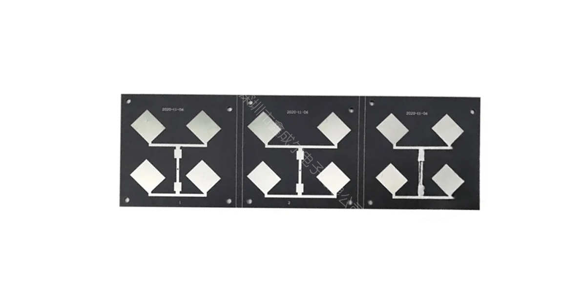
- Base-station antennas and feed networks — the loss floor and isotropic Dk make it a default for radiating structures and beamforming feed runs; the isotropy eliminates glass-weave skew that plagues woven reinforcements.
- mmWave backhaul and satellite terminals — Ku/Ka-band front ends where every 0.1 dB of feed loss is link budget; machining specifics in the satellite machining guide.
- Communications equipment broadly — the loss-budget arithmetic by device class is in the communication equipment analysis.
- Automotive — with the usual boundary: 5880 serves 24 GHz-class sensors and antennas; 77/79 GHz front radar standardizes on the RO4000 series (Z-CTE 32, rigid, FR-4 processing). The split is argued in the EV analysis.
Thermal Reality and the LZ Alternative
Thermal conductivity of 0.20 W/m·K is low — a 5880 antenna panel is not a heat sink, and high-power AAU front ends need thermal vias or metal-backed construction regardless of laminate choice. When the via-reliability side of Z-CTE 237 becomes the constraint, 5880LZ (Dk 1.96, Z-CTE 41.5, density 1.4) is the sanctioned exit — same PTFE family, ceramic-filled for dimensional stability, at the cost of slightly higher Df. The full comparison is in the 5880 vs 5880LZ selection guide.
What to Specify for a 5G/mmWave 5880 Build
- Core thickness by frequency — 0.127–0.254 mm for 28 GHz-class radiating structures; the seven-core table is in the thickness guide.
- Copper foil profile — low-profile foil for 28 GHz and above; conductor loss becomes comparable to dielectric loss at mmWave.
- Impedance verification — TDR coupons from the production panel; the ±0.02 Dk band only pays off if etch and plating hold their tolerances.
- Assembly thermal profile — PTFE is thermoplastic; reflow is fine but repeated excursions need review on thick-copper builds.
How XCE PCB Builds 5G/mmWave Boards
XCE PCB builds RT/duroid 5880 boards from 2 to 72 layers, impedance controlled to ±10%, panels up to 600 × 1200 mm, with sodium-naphthalene hole treatment as standard. Samples in as fast as 24 hours when laminate is in stock. Related: the laminate overview, the preferred-material case and the ultra-low-loss analysis.
Frequently Asked Questions
What is the CTE of RT/duroid 5880?
How much insertion loss does 5880 save versus FR-4 at 28 GHz?
Is 5880 good for high-power 5G amplifiers?
Quoting a 5880 Build?
Send us your Gerber files and requirements for a manufacturability review and a tailored quotation.
sales1@xcepcb.com
+86 180 3818 8537