
RO4003C is the lowest-loss laminate in the RO4000 family, and the reason it is everywhere in RF hardware is not just the datasheet — it runs on a standard FR-4 line with no PTFE handling. This guide covers where it is used, how it is actually fabricated, and the four points where the process differs from an FR-4 run.
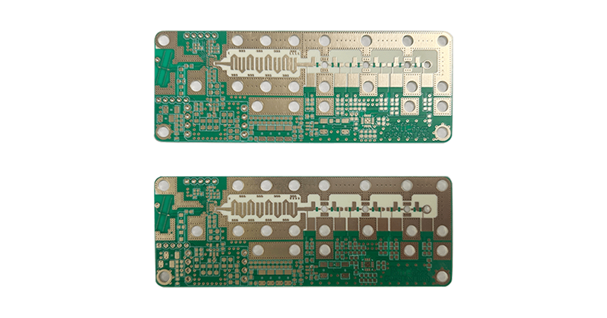
What RO4003C Actually Is
RO4003C is a woven-glass-reinforced, ceramic-filled hydrocarbon thermoset laminate — not a PTFE material, and not an epoxy/glass FR-4 either. Rogers describes it as combining the electrical performance of PTFE/woven glass with the manufacturability of epoxy/glass, and that one sentence explains nearly every decision around this material.
The electrical numbers that matter:
| Property (typical) | RO4003C |
|---|---|
| Dk, process @ 10 GHz | 3.38 ± 0.05 |
| Dk, design (for impedance work) | 3.55 |
| Df @ 10 GHz | 0.0027 (0.0021 @ 2.5 GHz) |
| TCDk, −50 to +150 °C | +40 ppm/°C |
| CTE X / Y / Z | 11 / 14 / 46 ppm/°C |
| Thermal conductivity | 0.71 W/(m·K) |
| Tg / Td | > 280 °C / 425 °C |
| Copper peel, 1 oz ED | 1.05 N/mm |
| Water absorption | 0.06% |
| UL 94 rating | None (non-brominated) |
| Standard cores | 0.203 – 1.524 mm (8 – 60 mil) |
One correction that circulates widely: RO4003C is sometimes described as glass-free or weave-effect-free. It is glass-reinforced — Rogers builds it on 1080 and 1674 glass fabric styles. The 1674 style is a fine, tightly woven fabric that keeps weave-induced Dk variation small, but it does not eliminate the mechanism. If a design is genuinely sensitive to fiber-weave skew — very high speed digital or precision phased-array feed work — the glass-free options are ceramic-filled PTFE laminates, which move you to a different process and a different cost structure.
Also worth stating plainly, because it rules the material in or out of many projects: RO4003C is non-brominated and carries no UL 94 rating. Where a flammability rating is required, the family answer is RO4350B at V-0. The full trade-off analysis is in our 4350B vs 4003C comparison.
Where RO4003C Is Used
The application map follows directly from two facts: Df 0.0027 at 10 GHz, and FR-4 process compatibility. It is the right answer wherever loss matters but PTFE handling is not justified:
| Field | Typical circuits | Why 4003C fits |
|---|---|---|
| Base station infrastructure | PA boards, filters, combiners, antenna feed networks | Low loss plus tight Dk tolerance for repeatable tuning across production lots |
| Automotive radar | 77 GHz radar sensors for AEB and adaptive cruise | Loss stays usable at mmWave; TCDk +40 keeps frequency drift bounded |
| Satellite & broadcast | VSAT receivers, LNB front ends | Low noise figure contribution at the receiver input |
| RFID / IoT | Reader antennas, gateway radios | Predictable impedance for antenna matching, FR-4 economics at volume |
| Passive microwave components | Couplers, dividers, LNAs | High-Q structures reward the 0.0027 loss tangent directly |
The one application pattern to handle with care is the hybrid cost strategy: RO4003C for the RF signal layers laminated to FR-4 for power and ground. It is a legitimate and widely used construction, but it moves the reliability risk to the interface between two materials with different Z-axis CTE — 46 ppm/°C against roughly 50–70 for FR-4 — and the stack-up needs to be engineered, not assumed.
Fabrication: The Standard Flow
The reason RO4003C displaced older microwave laminates in high-volume products is that almost nothing in the flow changes. The full sequence, with the notes that matter:
| Step | Guideline |
|---|---|
| 1. Panel prep & inner-layer imaging | Standard process. The laminate is harder and more brittle than FR-4 — handle panels to avoid edge chipping at cut and clamp points |
| 2. Lamination | Standard FR-4 prepregs (1080, 2116) work for multilayer bonding; for best interface reliability use the matched Rogers 2929 bondply. Bake laminates before lamination to drive off moisture |
| 3. Drilling | Standard carbide bits — no diamond coating required. Tune feed and speed for the ceramic filler, which wears bits faster than FR-4 |
| 4. Hole metallization | Standard permanganate desmear and electroless copper. No sodium-naphthalene or plasma activation — this is the step that PTFE materials demand and 4003C does not |
| 5. Outer-layer imaging & etching | Standard lithography and acid etch; foil adhesion is strong (1.05 N/mm peel), which helps etch uniformity |
| 6. Solder mask & surface finish | LPI solder mask as usual; ENIG, immersion silver, immersion tin, HASL or OSP all work — choose by frequency and assembly |
| 7. Routing & test | Score or route normally; flying-probe or fixture test as with FR-4 |
Where the Process Differs from FR-4
“FR-4 compatible” does not mean “identical.” Four points decide whether a 4003C build yields well:
1. Drilling against a ceramic filler. The filler that gives the laminate its stable Dk also abrades carbide faster than FR-4 resin. Bit hit-count limits need to be tightened, and resin smear on the hole wall is managed by feed/speed tuning rather than exotic chemistry.
2. Bondply choice. For all-RO4003C multilayer builds, Rogers 2929 bondply is the matched system. An arbitrary FR-4 prepreg can bond, but the interface is where delamination, unstable dielectric spacing and thermal-cycle failures concentrate. For hybrid builds the FR-4 prepreg decision is deliberate — see the hybrid material difficulties analysis.
3. Z-axis CTE in the stack-up. 46 ppm/°C is moderate, and it is fine for two to eight layers. On thick multilayer boards with many reflow cycles, it accumulates — that is the row where RO4350B (32 ppm/°C) earns its place. Stack-up symmetry matters more than usual: asymmetric copper distribution turns a moderate CTE into visible warp.
4. Impedance discipline. Dk is stable, but impedance comes from the design Dk (3.55), not the process value (3.38). Solvers fed with 3.38 produce widths about 3% narrow. Confirm with a TDR coupon on the production panel — calculation alone is not verification. The parameter-by-parameter breakdown is in the 4003C parameters and production guide.
Selection Advice
| If your requirement is… | Then |
|---|---|
| Frequency above roughly 1–2 GHz, loss or phase stability matters | Upgrade from FR-4 to RO4003C — FR-4’s Dk varies too much with frequency and temperature for controlled RF work |
| UL 94 flammability rating required by the end product | RO4350B (V-0). RO4003C cannot satisfy the requirement at any rating |
| Ultra-low loss, Df ≤ 0.002, and PTFE processing is acceptable | RO3003 (Dk 3.00, Df 0.0010) — higher material and processing cost, but a different loss class |
| Thick multilayer, many thermal cycles, via reliability critical | RO4350B — Z-axis CTE 32 vs 46 ppm/°C, plus cores down to 0.101 mm |
| Best balance of RF performance, cost and process convenience | RO4003C — this is exactly the gap it was designed to fill |
How XCE PCB Builds RO4003C
XCE PCB builds RO4003C for 2 to 72 layers, impedance controlled to ±10% and verified with TDR coupons on the production panel, on panels up to 600 × 1200 mm. Because the laminate runs on the same line as our FR-4 work, hybrid stack-ups — RO4003C signal layers with FR-4 planes, bonded and finished in one pass — are routine production rather than a special process. Samples in as fast as 24 hours when laminate is in stock.
Send the stack-up, frequency range and surface finish and we will confirm the build before quoting. For the commercial side of the material, see the 4003C advantages overview; for how it compares against RO4350B in detail, start from the family comparison.
Frequently Asked Questions
Is Rogers 4003C a PTFE material?
Does RO4003C have a fiberglass weave effect?
What is the difference between process Dk and design Dk on RO4003C?
Can RO4003C be bonded with normal FR-4 prepreg?
Does RO4003C meet UL 94 V-0?
What surface finish works best on RO4003C?
Need RO4003C Boards Built to Your Stack-Up?
Send us your Gerber files and requirements for a manufacturability review and a tailored quotation.
sales1@xcepcb.com
+86 180 3341 4657