
Most pages that discuss F4B high frequency PCB material treat it as one laminate. It is a designation system: a PTFE glass-cloth copper-clad family with three active branches and a nine-grade dielectric-constant ladder from 2.17 to 3.00, plus a ceramic-filled line that reaches 3.5. Picking the wrong rung of that ladder does not fail a board — it quietly changes trace width, loss and phase stability by amounts this article puts in numbers, and the two temperature coefficients at the end of it decide whether the family is usable in your environment at all.
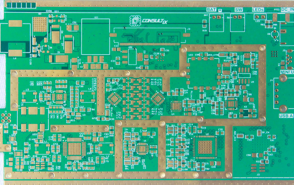
1. What the Letters F4B Actually Name
F4B is not a brand. It is the national-standard shorthand for a construction: F4 is the chemical designation for polytetrafluoroethylene (PTFE), and B stands for the copper-clad laminate board built on it, reinforced with woven glass cloth. Everything sold under this family — F4BM220, F4BME255, F4BTM300 and the rest — shares that PTFE-plus-glass-cloth construction, and the numbers and letters around it carry exact meanings:
F4BM220 reads as: PTFE board, M = glass-cloth reinforced grade, 220 = dielectric constant × 100, so Dk 2.20. The same rule gives F4BM255 a Dk of 2.55 and F4BM300 a Dk of 3.00. The legacy designation F4B220 (no M) is the predecessor grade; drawings that still call it out resolve to the current F4BM220. Each grade also exists with a reverse-treated copper foil as the F4BME branch, and with ceramic filler as the F4BTM branch — the full model list, including the legacy names, is maintained in the complete F4B sheet model list.
Two things follow from reading the name correctly. First, the grade number tells you the Dk before you open a datasheet. Second, any article that quotes “F4B” with a single Dk value — the original version of this page quoted 2.2–2.7 — has collapsed a nine-grade ladder into one number, and the corrections are in section 10.
2. Three Branches and What Each Letter Changes
The branches differ in construction, not in naming logic. Knowing exactly which physical change each letter represents matters, because two of the three branches have identical electrical data and still produce different antennas in the field.
| Designation | Construction | What the letters change | Electrical consequence |
|---|---|---|---|
| F4B (legacy) | PTFE + glass cloth, ED copper | Predecessor designation, no reinforcement letter | Superseded grade by grade (F4B220 → F4BM220) |
| F4BM | PTFE + glass cloth, ED copper | M = the current glass-cloth reinforced grade | Dk 2.17–3.00 ±0.04–0.06, Df 0.0010–0.0018 |
| F4BME | Same as F4BM, reverse-treated (RTF) copper | E = the foil, not the dielectric | Identical Dk/Df to F4BM; lower PIM |
| F4BTM | PTFE + glass cloth + ceramic filler | T = filled system | Dk 2.98–3.5, Df from 0.0018 |
| F4BM-AL | F4BM dielectric on an aluminium or copper base | AL = metal-backed single-sided build | Shielding and heat spreading; single-sided only |
The E branch is the one most often described wrong. Secondhand articles frequently call F4BME a “ceramic-filled” grade — it is not; its dielectric is the same glass-cloth PTFE, and the only change is the copper foil. Why a foil change alone is worth a separate branch is the subject of section 6, and the foil types themselves are compared in the PCB copper foil guide.
3. The Nine-Model Ladder
The F4BM branch ships nine Dk grades. The ladder is the family’s real product: a designer steps up in Dk to shrink geometry, and pays with Df, with Dk tolerance that loosens at the top of the range, and with temperature coefficients that improve as Dk rises. The full official ladder:
| Grade | Dk @10 GHz | Df @10 GHz | TCDk (ppm/°C) | Z-CTE (ppm/°C) |
|---|---|---|---|---|
| F4BM217 | 2.17 ± 0.04 | 0.0010 | −150 | 240 |
| F4BM220 | 2.20 ± 0.04 | 0.0010 | −142 | 240 |
| F4BM233 | 2.33 ± 0.04 | 0.0011 | −130 | 205 |
| F4BM245 | 2.45 ± 0.05 | 0.0012 | −120 | 187 |
| F4BM255 | 2.55 ± 0.05 | 0.0013 | −110 | 173 |
| F4BM265 | 2.65 ± 0.05 | 0.0014 | −100 | 142 |
| F4BM275 | 2.75 ± 0.05 | 0.0015 | −92 | 112 |
| F4BM294 | 2.94 ± 0.06 | 0.0017 | −85 | 98 |
| F4BM300 | 3.00 ± 0.06 | 0.0018 | −80 | 95 |
Three reading rules for the table. One: every grade in the family carries UL 94 V-0 rating and water absorption at or below 0.08 % (F4BM220 third-party confirmed data), so the ladder is not trading safety or moisture for Dk. Two: the TCDk column is negative throughout — Dk falls as temperature rises — and its magnitude shrinks from −150 to −80 as Dk climbs; the family is more thermally stable at the top of the ladder, not the bottom. Three: the Z-CTE column falls by 2.5× across the ladder, which matters for via reliability on thick boards — section 5 puts that in reflow numbers.
4. What the Ladder Buys: Geometry, Not Loss
The reason to climb the ladder is size. On a 50 Ω microstrip over a 0.254 mm dielectric, the trace geometry moves as follows:
| Dk | W/h for 50 Ω | εeff (microstrip) | λg at 10 GHz | αd at 10 GHz |
|---|---|---|---|---|
| 2.17 | 3.14 | 1.85 | 22.1 mm | 0.038 dB/in |
| 2.20 | 3.11 | 1.87 | 21.9 mm | 0.039 dB/in |
| 2.33 | 3.00 | 1.96 | 21.4 mm | 0.044 dB/in |
| 2.45 | 2.91 | 2.04 | 21.0 mm | 0.049 dB/in |
| 2.55 | 2.83 | 2.11 | 20.6 mm | 0.054 dB/in |
| 2.65 | 2.76 | 2.18 | 20.3 mm | 0.059 dB/in |
| 2.75 | 2.70 | 2.25 | 20.0 mm | 0.065 dB/in |
| 2.94 | 2.58 | 2.38 | 19.5 mm | 0.076 dB/in |
| 3.00 | 2.54 | 2.42 | 19.3 mm | 0.081 dB/in |
Read the two ends of the ladder against each other. Moving F4BM220 to F4BM300 narrows the 50 Ω line from 0.79 mm to 0.65 mm (−18 %) and shortens it by 12 %, so a resonator or a patch array shrinks by roughly 28 % in area. That is a real, layout-level saving.
What the ladder does not buy is loss. Dielectric loss per inch scales with √Dk × Df, and the two factors pull in opposite directions: the √Dk term adds only 8 % from 2.20 to 3.00, while the Df ladder itself climbs 80 % (0.0010 to 0.0018). Net result: dielectric loss per inch nearly doubles from the bottom rung to the top, against an FR-4 baseline of 1.08 dB/inch at 10 GHz — every F4B grade is still 13 to 28 times better than FR-4, but within the family the low-Dk grades are the low-loss grades. The impedance consequences of these widths, and what tolerance does to them, are treated in high-frequency PCB impedance control.
5. The Two Temperature Numbers That Define the Family Limits
Every PTFE glass laminate lives or dies on two coefficients, and F4B is no exception. The first is TCDk, the temperature coefficient of the dielectric constant. The second is Z-CTE, the through-thickness expansion rate. Both are numbers the marketing pages skip and the datasheets print.
TCDk and phase. At −142 ppm/°C (F4BM220), the Dk moves 2.8 % over a 200 K excursion — the −50 to +150 °C range an outdoor unit actually sees. On a 100 mm line at 10 GHz that is roughly 24° of phase drift, comparable with RT/duroid 5880 (−125 ppm/°C, about 21°) and an order of magnitude worse than RO3003 (−3, under 1°):
| Laminate | TCDk (ppm/°C) | ΔDk over 200 K | Δφ per 100 mm at 10 GHz |
|---|---|---|---|
| F4BM220 | −142 | 2.8 % | ≈24° |
| F4BM300 | −80 | 1.6 % | ≈13° |
| RO3003 (ceramic-filled PTFE) | −3 | 0.06 % | <1° |
| RT/duroid 5880 (PTFE, micro-fibre) | −125 | 2.5 % | ≈21° |
For power amplifiers and filter paths that drift is invisible. For a phased-array feed, a 24° run-to-run shift across temperature is a pointing error, and it is the single most common reason an F4B design gets requalified onto a ceramic-filled laminate. Within the family, climbing to F4BM300 halves the drift — one more reason the top of the ladder exists.
Z-CTE and the plated hole. At 240 ppm/°C, the Z axis of F4BM220 expands 14 times faster than copper. A 1.6 mm board crossing a 215 K reflow excursion grows about 83 µm through its thickness, and the plated barrel inside it has to stretch to follow:
| Laminate | Z-CTE (ppm/°C) | Z-growth, 1.6 mm over 215 K | Via design consequence |
|---|---|---|---|
| F4BM220 | 240 | ≈83 µm | Aspect ratio ≤6:1, high-elongation plating |
| RT/duroid 5880 | 237 | ≈82 µm | Same rules; treat as pure PTFE |
| RO4350B | 32 | ≈11 µm | Standard FR-4-class rules apply |
| RO3003 | 25 | ≈9 µm | Standard FR-4-class rules apply |
The two tables say the same thing from different directions: electrically F4B sits next to the best PTFE laminates; mechanically it must be manufactured like them. Aspect-ratio limits, high-elongation copper plating and desmear chemistry are not optional on this family. The comparison with the Rogers grades it is most often quoted against is laid out in the RT/duroid 5880 analysis.
6. F4BME: the Branch That Exists Because of PIM
Passive intermodulation (PIM) is what happens when a transmitter’s two carriers mix in a nonlinear junction and land in the receive band. In a base-station antenna feed, the dominant nonlinear junction is not a component — it is the microscopic interface between the copper and the dielectric, rough at the scale of standard electrodeposited foil.
The F4BME branch changes exactly one thing: the ED foil is replaced with reverse-treated (RTF) copper, bonded so that the dielectric side of the foil is the smooth drum side. The copper-glass interface becomes flat, the nonlinear contact area drops, and PIM performance improves measurably — which is why antenna manufacturers specify F4BME for feed networks while using F4BM for everything else. The Dk, Df, TCDk and Z-CTE columns are identical, grade for grade; there is no electrical penalty and no electrical benefit, and any datasheet claiming a Df difference between F4BM and F4BME is describing a foil lot, not a laminate grade.
7. F4BTM: When 3.0 Plus Is the Requirement
The ceramic-filled branch extends the ladder past 3.00 to a Dk range of 2.98–3.5. It exists for designs where the geometry ceiling matters more than the loss floor: compact antenna arrays, mmWave modules where the patch size sets the package, and circuits that would otherwise need a high-Dk Rogers grade to fit.
The cost is printed in the Df column: filled grades start at 0.0018, 80 % above F4BM220, the same trade the F4BM ladder itself makes internally. The filler does help the temperature coefficients — ceramic loading is how the negative PTFE TCDk gets pulled toward zero — so F4BTM is the branch to evaluate when a phase-critical design needs both a high Dk and a smaller TCDk than the F4BM ladder offers. Specific grade values should be confirmed against the current manufacturer datasheet before they go on a drawing; the official table does not publish the full F4BTM per-grade breakdown in the same detail as the F4BM ladder.
8. Where F4B Sits Against Rogers and Taconic
F4B has no one-to-one Rogers equivalent, and treating it as “cheap 5880” or “Chinese 3003” produces wrong specifications. The honest anchor points for the most-specified grade:
| Property | F4BM220 | RO3003 | RT/duroid 5880 |
|---|---|---|---|
| Dk @10 GHz | 2.20 ± 0.04 | 3.00 ± 0.04 | 2.20 ± 0.02 |
| Df @10 GHz | 0.0010 | 0.0010 | 0.0009 |
| TCDk (ppm/°C) | −142 | −3 | −125 |
| Z-CTE (ppm/°C) | 240 | 25 | 237 |
| Construction | Glass-cloth PTFE, ED copper | Ceramic-filled PTFE, no glass | PTFE, micro-fibre |
F4BM220 lands electrically beside 5880 — same Dk, near-same Df — and inherits the same two temperature weaknesses. RO3003 trades glass cloth for ceramic filler and buys back both coefficients at the cost of a higher Dk. Whether that trade is worth it for a given programme is a four-threshold question (Dk tolerance, TCDk, Z-CTE, peel strength) rather than a price question; the arithmetic is worked through in the Rogers-versus-PTFE selection guide, and the same comparison expanded across four laminate vendors, including Wangling (旺灵), the source of the F4B grades, is in the four-vendor material comparison.
9. A Selection Map by Job
With the ladder and the branches in hand, most selections resolve to one row of this table:
| The job | Default grade | Why this rung |
|---|---|---|
| Cost-sensitive microwave front ends, volume builds | F4BM220 | Lowest Df on the ladder, tightest tolerance, best-documented grade |
| Base-station antenna feeds, PIM-critical paths | F4BME220/255 | Same electricals as F4BM; RTF copper lowers PIM |
| Compact patches, size-limited mmWave modules | F4BM265–300 or F4BTM | −18 to −28 % area versus 2.20; pay in Df and tolerance |
| Phase-critical arrays over wide temperature | F4BM300 or F4BTM | TCDk −80 or better versus −142 at the bottom of the ladder |
| Thermal spreading or shielding, single-sided | F4BM-AL | Metal base without a separate heatsink assembly |
| Legacy drawing calls out F4B220/255/265 | F4BM-equivalent | Direct successors; confirm foil weight and thickness, not the name |
The grade-specific pages carry the per-model depth: the F4BM220 introduction for naming and first-read parameters, and the F4BM220 specifications page for parameter-to-impedance arithmetic. The 2.55 rung and its miniaturisation trade-off have their own page in this series.
5 Claims This Page Used to Make, Corrected
The previous version of this article was a list of adjectives. Rewriting it against the manufacturer datasheet changed several of its claims; the corrections are kept visible because the same errors circulate in most secondhand F4B content:
| Original claim | Corrected fact |
|---|---|
| “Dk typically ranging from 2.2 to 2.7” | The F4BM ladder spans 2.17–3.00; the F4BTM branch extends to 3.5. 2.2–2.7 is four rungs of nine. |
| “Maintains dimensional stability without significant expansion” | Z-CTE is 240 ppm/°C — 14× copper. A 1.6 mm board grows ≈83 µm in reflow. Stable in X/Y, deliberately not in Z. |
| “Excellent thermal stability” | TCDk −142 ppm/°C: Dk moves 2.8 % over 200 K, ≈24° of phase per 100 mm at 10 GHz. “Stable” is the one thing it is not, in the RO3003 sense. |
| “Used in MRI” | MRI RF sits at 64–298 MHz, where even FR-4 loss is negligible. The real medical requirement is repeatability and thermal stability of the build, not low Df. |
| “Used in 77 GHz automotive radar” | 77 GHz front-radar programmes predominantly run RO4000-class laminates for process compatibility. F4B’s realistic share is antenna layers and cost-driven modules, stated without the blanket claim. |
11. Fabrication Notes That Follow from the Family
Two manufacturing facts come with the family regardless of grade. First, the glass cloth is an asset: it gives the laminate stiffness and drilled-hole quality that pure PTFE lacks, which is why F4B tolerates thin cores and dense layouts better than a glass-microfibre construction of the same Dk. Second, it is still PTFE: holes need sodium naphthalenide or plasma desmear, laser cutting is off the table, and any hybrid press with FR-4 has to respect the two-chemistry problem (PTFE bonds at 260–300 °C with FEP-based systems; epoxy cures at 170–190 °C).
Grade-specific process windows — desmear recipes, drill parameters, press cycles and the FR-4 hybrid sequence — are covered in the F4BM220 processing page. If the decision at hand is between this family and an imported laminate rather than between F4B grades, start from the material selection framework and bring the loss budget, not the brand list.
12. Conclusion
F4B is a nine-rung ladder inside a three-branch designation system, and every decision about it reduces to reading the name correctly. The rung sets the geometry: 3.11 W/h at 2.20 against 2.54 at 3.00, a 28 % area saving for an antenna that must fit. The Df column sets the loss: 0.039 dB/inch at the bottom of the ladder against 0.081 at the top, all of it far under FR-4’s 1.08. The two temperature numbers set the limits: TCDk −142 ppm/°C and Z-CTE 240 ppm/°C make the family a PTFE-class manufacturing problem even though its electricals sit beside the best laminates on the market.
XCE PCB builds F4B and hybrid stacks to those numbers: 2 to 72 layers, panels to 600×1200 mm, impedance ±10 % as standard with coupon-verified tighter windows, PTFE desmear and press capability in-house, samples in as fast as 24 hours, 5,000 m² of plant with 80+ engineers and more than 10,000 high-frequency builds since 2009, inspected to IPC-A-600G and IPC-6015. Send the grade number, the frequency and the environment the board must survive, and the ladder can be walked before anything is quoted.
Frequently Asked Questions
Is F4B the same material as Rogers RT/duroid 5880?
What does the number in F4BM220 mean?
What is the actual difference between F4BM and F4BME?
What are F4B real temperature limits?
Which F4B grade should I pick for a compact antenna?
Can F4B replace Rogers laminates in an existing design?
Send Us the Grade Number and the Frequency
Send us your Gerber files and requirements for a manufacturability review and a tailored quotation.
sales1@xcepcb.com
+86 180 3341 4657